Install Autopilot (AP) Control Panel
100048-00
Use the following procedure to install the Autopilot (AP) control panel.
Applicable Aircraft Serial Numbers
00139+ (Applicable to the Autopilot Configuration Only)
Type of Maintenance
Line
Level of Certification
LSA-RM
Task Specific Training Required
No
Special Tools Required
None
Parts Required
ME000622-NSG3X (BEZEL PAD PRINTED ASSY, CENTER STACK)
2x IUC-440-2 (INSERT, THREADED, TAPERED, 4-40X.219)
6x IUC-632-2 (INSERT, THREADED, TAPERED, 6-32X.250)
ICA013683 (INDICATOR, TRIM POSITION)
ICA014828 (BRACKET, AUTOPILOT, GMC 507, GARMIN)
ICA014703 (CONTROLLER, AUTOPILOT FLIGHT CONTROL SYSTEM, GMC 507, GARMIN)
6x 6C50MTT3 (SCREW, MACH TRH, 6LOBE, CRES, 6-32X.5000)
ME001906 (BLANK, AUTOPILOT)
TY24MX (CABLE TIE)
Aircraft System and Number
NA
Safety Equipment
As Needed
Consumables
ICA012078 (LUBRICANT)
Task Instructions
1. Heat stake the threaded inserts into the radio stack bezel flush +.010/-.03 as shown. Install inserts in the orientation shown, leading with the tapered side into the hole.
a. Heat the soldering iron to approximately ~700°F.
b. Set the insert into the hole with the tapered side down.
c. Using the pre-heated soldering tip, gently press the insert into the indicated hole until the insert is flush +.010/-.03.
d. Repeat for remaining inserts.
Figure 9. Heat Stake Inserts
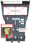
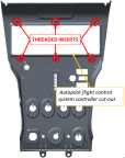
2. Install 2x 4-40 inserts landing gear position indicator cutout.
3. Install 6x 6-32 inserts around autopilot flight control system controller cutout as shown.
4. Install trim indicator.
a. Drill open trim indicator mounting holes using #50 drill bit (.070”Ø) x .5”-.75” deep.
Figure 10. Drill Open Trim
b. Remove trim position indicator from factory housing by temporarily removing 2x screws. Discard factory housing and save 2x screws.
Figure 11. Install Trim Indicator
c. Test fit the trim position indicator into the radio stack bezel. If the LED indicators do not fit through the slots in the bezel, use a small jeweler’s file to clean up any plastic material that causes the interference. Install trim position indicator into radio stack bezel using the 2x screws removed in the previous step. Apply lubricant liberally to the threads and shanks of 2x screws.
Figure 12. Test Fit Trim Position
AP Only
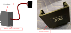
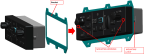
5. Install the autopilot flight controller into bracket.
6. Locate two mounting opening on LH and RH edge of the controller, use a 3/32” hex drive tool, turn clockwise to latch to autopilot until tightened to 20± 2 in-lbs.
Figure 13. Autopilot Flight Controller
7. Apply lubricant liberally to threads and shanks of 6x screws.
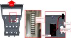
8. Locate the six threaded inserts on the radio stack bezel. Install the Garmin Autopilot Flight Control System Controller using 6x screws.
Figure 14. Threaded Inserts
9. Torque screws to 6.5-8.0 in-lbs.
G3X Only
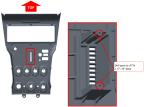
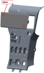
10. Install autopilot blank into center stack bezel by clipping LH side first and the pushing RH side into face of center stack bezel until snap feature engages.
Figure 15. Autopilot Blank
AP and G3X
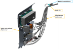
11. Secure TB9010 terminal block to wire harness with cable-tie.
Figure 16. Secure Terminal Block with Cable-Tie
Verification Method
Autopilot control panel has been installed.
Parent topic