Garmin G3X and Autopilot Bezel Installation
100061-00
Use the following procedure to install the Garmin G3X and Autopilot Bezel.
Applicable Aircraft Serial Numbers
00139+
Type of Maintenance
Line
Level of Certification
LSA-RM
Task Specific Training Required
No
Special Tools Required
None
Parts Required
ME001110-A (G3X BEZEL, HEAT STAKED, SUBASSY)
4x 8C50MTT3 (SCREW, MACH TRH, 6LOBE, CRES, 8-32X.250)
2x 6C50MTT3 (SCREW, MACH TRH, GLOBE, CRES, 6-32X.375)
Aircraft System and Number
05—Equipment and Furnishings
Safety Equipment
As Needed
Consumables
Loctite 243
Task Instructions
1. Using isopropyl alcohol, clean surfaces where lubricant will be applied. Apply Loctite 243 to threads and shanks of 4x screws.
2. Install G3X Bezel onto the top of the center console using the screws as shown fastened to threaded inserts in the bezel.
Figure 77. G3X Bezel
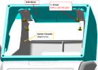
3. Torque screws to 12-14 in-lbs.
4. Using isopropyl alcohol, clean surfaces where lubricant will be applied. Apply lubricant liberally to threads and shanks of 2x screws.
5. Install the two screws through the bottom of the G3X Bezel and the slots in the Radio Bezel and into the installed nutplates in the center console.
Figure 78. G3X Bezel
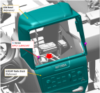
6. Torque screws to 6.5-8.0 in-lbs.
Verification Method
Procedure is complete when G3X Bezel is installed and ready to install the G3X display.
Parent topic