Elevator Bushing and Bearing Installation
100721-00
The following instructions are used to install the elevator bushing and bearing.
Applicable Aircraft Serial Numbers
All
Type of Maintenance
Line
Level of Certification
LSA-RM
Task Specific Training Required
No
Special Tools Required
None
Parts Required
2 X M81934/1-04C008 (BEARING, SLEEVE, PLAIN, SLFLBR, CRES, .250X.250X.435)
2 X ICA008532 (BUSHING, .191X.250X.435)
2 X NAS75C3-004 (BUSHING, PLAIN, CRES, .190X.313X.125)
2 X ICA009413 (BUSHING, FLANGED, .191X.375X.040)
2 X AN3C10A (BOLT, MACH, CRES, 10-32X.625)
5 X 92217A439 (WASHER, CRES, .1875X.625X.03)
2 X MS21043-3 (NUT, SLFLKG, RDC HEX, CRES, 10-32)
4 X MS24694C54 (SCREW, MACH FLH, 6LOBE, CRES, 10-32X.750X.313)
1 X ICA009408 (BUSHING, FLANGED, .191X.375X.070)
1 X MS27640-3 (BEARING, BALL, AFR AFB, HD, .190X.777X.297)
1 X ICA009409 (BUSHING, PLAIN, .191X.375X.188)
1 X AN3C11A (BOLT, MACH, CRES, 10-32X.750)
Aircraft System and Number
06—Flight Controls
Safety Equipment
As Needed
Consumables
ICA012078 ( GENERAL LUBRICANT)
LOCTITE 243 (THREADLOCKER, PRIMERLES, OIL TOL, REMOVABLE MED STR, BLUE
Torque Stripe
Hysol, EA 9394 (Structural Bonding Adhesive, Room Temperature Cure)
Task Instructions
1. Apply Hysol EA 9394 to the bearing (M81934/1-04C008).
2. Press bearing into Outboard Elevator Hinge, serialized. Clean excess adhesive and allow it to cure as per manufacturer’s instructions.
3. Install bushing (ICA008532) into bearing.
Figure 202. Install Bushing into Bearing
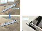
Note:
Elevator hinges should be installed with countersunk holes facing outboard.
4. Apply Hysol EA 9394 to the outer race of the bearing (MS27640-3) and press it into the center elevator hinge bracket. Ensure bearing is centered in the bracket. Clean excess adhesive and allow it to cure as per manufacturer’s instructions.
5. Install LH/RH Outboard Elevator Hinge onto elevator with previously removed hardware, bolt through bushing, bushing (previously installed), 2x washers and nut.
Figure 203. Install LH/RH Outboard Elevator Hinge
6. Install LH/RH Outboard Elevator Hinges onto HT with 2x screws.
7. Torque screws to 26 in-lbs. and apply torque stripe.
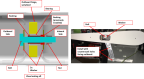
8. Connect Elevator Center Hinge on the HT using bolt with lubricant and washer threaded into nutplate as shown.
Figure 204. Connect Elevator Center Hinge
9. Torque bolt to 26 in-lbs. and apply torque stripe.
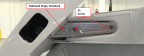
Figure 205. Hinge Mount Access Hole

Note:
Run clevis and jam nut all the way down to pushrod. Do not bend cutter pin prongs. These parts will need to be removed during the rigging process.
10. Temp install pushrod clevis to trim tab using pin, washer, and cotter pin.
11. Tape cotter pin in place so that it does not get lost.
12. Final install of pushrod clevis to trim tab using pin, washer, and cotter pin will be performed after Elevator Trim Rigging. (Inspect
Pitch Trim Tab Rigging)
Figure 206. Final Installation of Pushrod
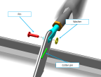
15. Install pushrod clevis to trim tab using pin, washer, and cotter pin.
16. Install components in the reverse order for removal.
Verification Method
Verify bind free movement of the elevator.
Parent topic