Install Exhaust System (00001-00109)
100161-01
Use the following procedure to install one side of the exhaust system. Repeat the procedure to install both sides of the exhaust system.
Applicable Aircraft Serial Numbers
00001-00109
Type of Maintenance
Line
Level of Certification
LSA-RM
Task Specific Training Required
No
Special Tools Required
None
Parts Required
ICA013354 (CLAMP, WORM DRIVE, NORMA TORRO, .35X1.19-1.75, SPRING INSERT
Aircraft System and Number
13—Propulsion
Safety Equipment
As Needed
Consumables
LOCTITE®243 (THREADLOCKER, PRIMERLESS, OIL TOL, REMOVABLE MED STR, BLUE)
ICA012067 (LUBRICANT, ANTI-SEIZE, NICKEL GRADE)
ICA012078 (LUBRICANT, GENERAL PURPOSE) Tef-Gel®
Task Instructions
1. Remove all dust plugs from the four exhaust ports on the engine (if installed).
2. Apply LUBRICANT, ANTI-SEIZE around the perimeter and up to 2 inches from the end of the FWD header.
3. Install FWD header onto the engine exhaust port studs using two new M8 copper lock nuts, leaving nuts slightly loose to allow for later adjustment.
Note:
The M8 lock nuts are for single use.
4. Disconnect the engine wire harness from the FWD intake manifolds by removing the M6 screw and washer. Save for later step.
5. Attach support bracket to header using the noted clamp and hardware.
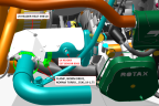
6. Attach other end of support bracket and engine wire harness to intake manifold using M6 screw and washer (previously removed). Apply THREADLOCKER. Position wire harness clamp with flat side down on top of exhaust bracket as shown in Figure 388.
Note:
The left and right bracket tubes are different.
7. Tighten the M8 copper nuts attaching FWD header to engine incrementally until header is fully seated. Torque both header nuts to 133 in-lb.
9. Torque the M6 screw to 90 in-lb.
10. Install header heat shield onto FWD header using 2x CLAMP. Align cutout in heat shield with EGT sensor boss on FWD header. Orient CLAMP such that the spring insert rests on both heat shield supports.
11. Torque 2x CLAMP incrementally up to 27-31 in-lb to prevent deflection of heat shield.
Figure 389. Header Heat Shield Installation
12. Clean and apply LUBRICANT, ANTI-SEIZE to threads of EGT sensor nut.
13. Attach EGT sensor to FWD header boss and torque to 19 ft-lb (228 in-lb) with a 17 mm wrench.
14. Install muffler shield (inner cowl), and secure with #15 Torx countersunk screw below FWD header. Apply LUBRICANT, GENERAL PURPOSE and torque screws to 26 in-lb.
15. If the mufflers are not already assembled to the aft headers as a sub-assembly, perform the following steps:
a. Clean the slip joint interfaces of muffler and aft header.
b. Apply a thin coat of LUBRICANT, ANTI-SEIZE to the slip joint interfaces.
c. Install AFT headers into the associated muffler. The anti-rotation tabs should overlap so that the tab on the muffler lies outboard of the tab on the header.
Note:
The mufflers and headers are not left/right interchangeable.
Secure aft header to muffler using MS20995C41 safety wire.
e. Wrap safety wire through the overlapping hole and over the top of the tabs three times, pulling it tight.
f. Then, wrap the wire through the overlapping hole and then through the aft hole in the header tab three times, pulling it tight.
g. Twist the ends of the wire together per standard practice and bend free end over to avoid a poke hazard.
16. Clean pipe and apply a thin coat of LUBRICANT, ANTI-SEIZE to the last 2 inches of FWD and AFT headers.
17. Install the muffler sub-assembly by sliding it forward onto the FWD header and onto the engine exhaust port studs.
18. Install new M8 copper lock nuts in two places on each header and tighten them incrementally until header is fully seated, then torque to 133 in-lb.
19. Clean and apply LUBRICANT, ANTI-SEIZE to threads of EGT sensor nut.
20. Attach EGT sensors to AFT header boss and torque to 19 ft-lb (228 in-lb) with a 17 mm wrench.
21. Repeat Steps 2-20 for LH/RH exhaust.
22. Install muffler fairings, tail pipe bezel, lower cowl, and engine cowl. (Install
Engine Cowlings)
Verification Method
After installation perform an engine test run in accordance with Engine Test Run paying particular attention to exhaust leaks.
Parent topic