Extraction Rocket Assembly and Installation
100164-01
Use the following tasks to install the extraction rocket system.
Applicable Aircraft Serial Numbers
All
Type of Maintenance
Line
Level of Certification
LSA-RM
Task Specific Training Required
No
Special Tools Required
None
Parts Required
1/4”-20 x 3/4 Button HD Cap SS
8-32 x 3/4 Screw
Aircraft System and Number
16—ICON Parachute System (IPS)
Safety Equipment
As Needed
Consumables
LOCTITE®242™
Warning:
Contact ICON Support before beginning maintenance.
Task Instructions
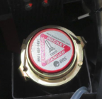
1. Mount the rocket pedestal with the rocket into the rocket bay. Secure the BRS 601 rocket assembly to ICON’s rocket mounting bracket using two of the BRS provided 1/4”-20 x3/4 Button HD Cap SS fasteners. Ensure that LOCTITE Blue 242 threadlocker is used to lock the fasteners in place. The torque value for the fastners is 5.4lb-ft. The fitting between BRS 601 fixing to the rocket mounting bracket should not allow rocket assembly to move in its mount, the two bolts should be enough to do so.
Note:
If the thickness of the mounting bracket allows BRS 601 movement after tightening the two bolts it is acceptable to use spacer to fully secure the rocket to the bracket.
Figure 497. Secure Rocket to ICON A5 Rocket Mount Bracket
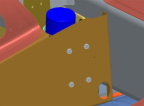
2. Fasten the rocket mount into the proper location in the ICON A5. Four AN3 bolts secure the rocket mount to the starboard center root rib.
Figure 498. Secure Rocket Mount to Starboard Center Root Rib
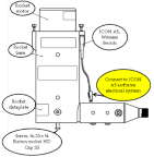
3. Connect electrical witness switch installed on the side of the rocket tube assembly to ICON A5 airframe electrical system.
Figure 499. 90° Rocket Assembly
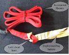
4. The rocket lanyard is already attached to the deployment bag at BRS Aerospace. The rocket lanyard will need to be routed and attached to the BRS 601 rocket in the ICON A5 rocket bay. Once the required length of lanyard is determined, the remaining length should be “looped” and secured with the small cable ties supplied. The rocket lanyards should be routed alongside of, rather than over the top of the rocket. They MUST NOT be routed under any harness or structure. Coil the lanyards without knotting them. Place the two cable ties around the lanyards so that they can be neatly stowed.
Figure 500. Securing Rocket Collar Lanyard and Incremental Harness
5. Ensure that the opposite end of the incremental harness, shown in under the left side flap, is connected to the deployment bag with a Lark’s head knot.
Figure 501. Incremental Harness to Deployment Bag Strap
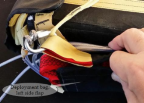
6. All items are secured under the left side flap of the deployment bag, using the installed Velcro® fasteners at the top side of the deployment bag.
Figure 502. Deployment Bag, Left Side Flap
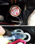
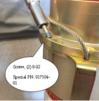
7. Connect rocket collar to the rocket tube. Insert and tighten screws, screw, 8-32 x 3/4, Special. These screws have been manufactured to shear when rocket is fired. Apply a small amount of LOCTITE Blue 242 threadlocker to threads. Torque fasteners to 5 in-lbs.
Warning:
Confirm that the safety pin and flag are installed in the activation handle before continuing to rocket installation section.
Figure 503. Securing Rocket Collar to BRS 601 Rocket Tube
Verification Method
The procedure was completed when the component has been installed and the safety pin and flag are installed on the activation handle.
Parent topic