Harness Installation
100251-00
Use the following tasks to place and route the harness system.
Applicable Aircraft Serial Numbers
All
Type of Maintenance
Line
Level of Certification
LSA-RM
Task Specific Training Required
No
Special Tools Required
None
Parts Required
008007-01 (Assy., Packed Parachute, A5)
014105-01 (Collar Assy., Pickup, Short Support)
005061-01 (Link, Quick, 1/2”, French SS)
001432-01 (Retaining Strap, A5)
007596-22 (Bridle, Kevlar, “A-C” End, Compact Tang)
007596-23 (Bridle, Kevlar, “A-C” End, Compact Tang)
ICA009063 (PIN, TIE OFF, CAP)
VH-62-S16 (Retaining Ring, Internal, Light Duty, 316ss, .656x.0118)
5X 004000-01 (Cable Tie, 10.75”)
Aircraft System and Number
16—ICON Parachute System (IPS)
Safety Equipment
As Needed
Consumables
LOCTITE®242
red zip tie
Task Instructions
1. Attach the “A” end of the rear harness to the mounting bracket located inside the parachute bay on the STARBOARD side of the aircraft.
Figure 485. Harness Assembly Attachment Points, Component View
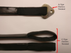
Figure 486. “A” End of Harness Attachment Point (STARBOARD REAR)
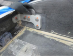
2. Attach the “A” end of the forward harness to the forward attachment bracket on the STARBOARD side of the aircraft with the tie off pin and retaining ring.
Figure 487. “A” End of Harness Attachment Point (STARBOARD FORWARD)
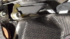
3. Attach the “A” end of the forward harness to the mounting bracket PORT side of the aircraft with the pin and the retaining ring.
Figure 488. “A” End of Harness Attachment Point (PORT FORWARD)
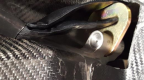
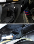
4. Route the AFT harness into the parachute bay to be “S”-folded and routed to the 1/2” quick link and attached to the riser later in the parachute installation bay. (The STARBOARD AFT harness mount point is located in the parachute bay.)
Figure 489. Harness Routing, AFT, STARBOARD harness to Parachute Bay
5. Route FORWARD PORT and STARBOARD harnesses into the parachute bay to be “S”-folded with the STARBOARD rear attachment point harness and routed to the 1/2” quick link then attached to the riser later in the parachute bay.
6. FORWARD PORT harness mount locations, total 2.
Figure 490. FORWARD PORT Harness Mount Locations
7. FORWARD STARBOARD harness mount locations, total 3.
Figure 491. FORWARD STARBOARD Harness Mount Locations
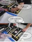
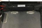
8. Install packed parachute assembly (Item 4) into parachute bay. Pin Release Tether and Retaining straps are shown below, attached to deployment bag. Rocket collar and lanyards can also be seen.
Figure 492. Harness Routing, AFT, PORT Harness to Parachute Bay
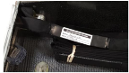
9. Connect harnesses with 1/2” quick link. Riser can also be seen on the right side of the deployment bag. Apply LOCTITE Blue 242 threadlocker to the threads before closing the gates. A torque of 20 lb-ft to shut the quick link. Since this product does not have a standard torque value, ensure that all threads are engaged. Finally, check that hardware is secure.
Figure 493. Harness Ends Inserted into 1/2” Quick Link
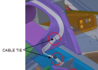
10. Lay the S-folded harnesses together as a package fixed with (2) two, 10.75” cable ties (004001-01), into the parachute bay.
Note:
Only approved cable ties can be used to secure harnesses.
Note:
Use care to ensure that harnesses are neatly S-folded and will be free from restrictions during recovery system deployment.
Note:
Ensure only the noted 004001-01 cable ties are present when installation is COMPLETE.
11. Route the two forward parachute harnesses over the rocket mount, over the chicken track, and then down through the side of the parachute.
12. Fold and secure aft harnesses. Measure 16” from the “C” end of the aft harness. Place the “C” end of the harness on the outboard side of the parachute box. From here begin the “S fold. S-Fold the harness so that the “C” end is on top of the stack. S-Fold the aft harness so that each layer is 16” in length. Use temporary cable ties to hold this bundle while the other harnesses are folded. With this bundle made, loosely attach a temporary red cable tie to the “C” end so that it can easily be identified.
13. Fold and secure RH fwd harness. Measure 14” from the “C” end of the RH forward harness. Place the “C end of the harness on the outboard side of the parachute box. From here begin the S-Fold. S-Fold the harness so that the “C” end is on the top of the stack. S-Fold the RH forward harness so that each layer is 14” in length. Use temporary cable ties to hold this bundle while the other harnesses are folded. With the bundle made, loosely attach a temporary red cable tie to the “C” end so that it can be easily identified.
14. Fold and secure LH fwd harness. Measure 16” from “C” end of the LH forward harness. Place the “C end of the harness on the outboard side of the parachute box. From here begin the S-Fold. S-Fold the harness so that the “C” end is on the top of the stack. S-Fold the LH forward harness so that each layer is 16” in length. Use temporary cable ties to hold this bundle while the other harnesses are folded. With the bundle made, loosely attach a temporary red cable tie to the “C” end so that it can be easily identified.
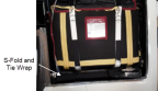
15. Insert the harness package into the space between parachute and parachute cover. Three harnesses will be “S” folded into space AFT of the parachute bag in the ICON parachute bay and placed in the bay as a unite tied together with (2) two, 10.75” cable ties.
Figure 494. Harness Installation: “S”-Fold and Tie Wrap
Note:
When installing the parachute bag into the compartment, use care to be sure that bridles are neatly “S” folded and will be free from restrictions during recovery system deployment.
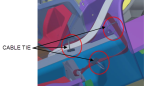
16. With the three harnesses neatly S-folded and stacked on top of one another secure all three folded harness stacks to the cable tie mounts together as a package fixed with 2X Cable Tie (004000-01).
Figure 495. Harness Stacks in Order
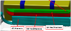
Figure 496. Photo Example
17. Attach “C” ends of LH fwd RH fwd, and aft harnesses o 1/2” quick link.
18. Using isopropyl alcohol, clean surfaces where threadlocker will be applied. Apply threadlocker to threads of 1/2” quick link. Torque to 240 in-lbs.
19. Remove and discard temporary red cable ties.
Verification Method
Verify that the release pins have not been damaged and have not been tampered with. The procedure is complete when the harness has been successfully installed and all components are secure.
Parent topic