Inspect Rudder Pedal Adjustment Mechanism
100310-00
The following section contains information needed to inspect the rudder pedal adjust mechanism for correct function.
Applicable Aircraft Serial Numbers
All
Type of Maintenance
Line
Level of Certification
LSA-RM
Task Specific Training Required
No
Special Tools Required
None
Parts Required
None
Aircraft System and Number
06—Flight Controls
Safety Equipment
As Needed
Consumables
None
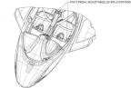
Figure 80. Rudder pedal latch locations under pilot and co-pilot seats.
Task Instructions
2. Pull the lever under the seat as shown
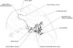
Figure 81. Rudder pedal latch locations under pilot and co-pilot seats.
3. Ensure pedals completely move aft via a gas strut upon pulling the lever.
4. Release lever.
5. Push on pedals to obtain positive engagement.
Note:
Positive engagement is reached when pedals cannot be moved while applying load on heel strike.
6. Ensure the rudder cables going through the floor are free to operate and the pedals move freely.
7. Pull the lever again and unlock the locking mechanism.
8. Push with heel on heel strike in between the pedals on floor.
9. Confirm pedal assembly moves forward freely with ~30 lbs of force.
10. Release handle and load on heal strike and ensure positive engagement.
11. Ensure the rudder cables going through the floor are free to operate and the pedals move freely.
13. Repeat this process for the co-pilot seat.
Verification Method
Verify that results are within acceptable limits.
Parent topic