Install G3X ADS-B Antenna
100325-01
Use the following procedure to install the ADS-B antenna. This task is applicable to the Garmin G3X configuration only.
Applicable Aircraft Serial Numbers
00139+
Type of Maintenance
Line
Level of Certification
LSA-RM
Task Specific Training Required
No
Special Tools Required
None
Parts Required
ICA014925 (ANTENNA, ADS-B, GPS/WAAS, GA 35, GARMIN)
8C100MTF3/100 (SCREW, MACH FLH, 6LOBE, CRES, 8-32X1.00)
NAS1149CN816R (WASHER, FLAT, CRES, 38X.016, PSVT)
MS21043-08 (NUT, SLFLKG, RDC HEX, CRES, 8-32)
ICA014926 (GROUND WIRE, ADS-B GPS, 18 AWG, 8.00)
Aircraft System and Number
10—Instruments (and Avionics)
Safety Equipment
As Needed
Consumables
ICA012078 (LUBRICANT, GENERAL PURPOSE)
CB200 (ADHESIVE, ACRYLIC STRUCTURAL, 2 PART, CLICK BOND, 3.5 GRAM PACKET)
ICA012218 (ADHESIVE SEALANT, WHITE)
ICA013211 (WAX, CARNAUBA)
ICA012218 (SIKAFLEX ADHESIVE)
Figure 276. Engine Cowling
Task Instructions
1. Prep Garmin antenna and top cowl for potting by completing the following:
a. Apply carnauba paste wax onto mating surfaces of antenna and cowling. Do not wax inside of or on O-ring.
b. Allow 5 minutes for the wax to flash off.
c. Wipe carnauba wax off using a lint free cloth to leave thin film of residue on the mating surfaces.
d. Repeat the previous steps a total of three times.
2. Apply adhesive sealant, around 4x mounting holes locations and center -ring of the Garmin antenna. Apply enough Sikaflex to fill gap between antenna and cowl.
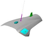
3. Position Garmin antenna on cowl with coax connector inserted in the center hole. Ensure antenna is oriented as shown.
Figure 277. Position of antenna on Engine Cowling
4. Using isopropyl alcohol, clean surfaces where lubricant will be applied.
5. Apply lubricant liberally to threads and shank of screw.
Figure 278. Apply Lubricant and Secure Antenna
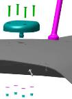
6. Secure antenna using noted hardware.
7. Torque nut to 13-15 in-lbs. Ensure at least one full thread is protruding from the nut.
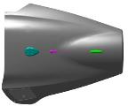
8. On the lower unpainted side of cowl orient 2x ground wires 90° from one another as shown. Temporarily secure ground wires using tape in the approximate location shown.
Note:
Ensure ground wires are stretched along the lower side of engine cowl and oriented as shown.
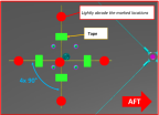
9. Mark the 5x locations on the ground wires where CB200 will be applied as shown.
Figure 279. Engine Cowl
10. Prepare cowl bonding surface:
a. Mask surrounding area as required.
b. Wipe bonding surface with isopropyl alcohol using 2-wipe method.
c. Lightly abrade bonding surface using 120-180 grit sandpaper.
Note:
Do not abrade more than .25” beyond bond area.
Note:
Abrade carbon surface just enough to remove surface gloss.
d. Blast surface with shop air to remove any remaining particulate residues.
e. If any dust remains, wipe bonding surface again using isopropyl alcohol.
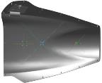
Figure 280. Applying G3X Antenna to Engine Cowl
11. Using CB200 adhesive, bond 2x ground wires to cowl surface at locations shown with 1/2 normal diameter dollop/blob.
a. Ensure adhesive is completely mixed before it is applied.
Note:
Use mixed adhesive within 5 minutes. Multiple batches may be required.
Note:
Ensure that there is squeeze out around the entire perimeter.
b. Allow adhesive to cure for a minimum of 30 minutes before handling and 2 hours before installing hardware.
Note:
Apply uniformly for better result and do not cover the labels.
12. Allow adhesive to become tacky before removing tape. Use caution to ensure wires do not get pulled out of the adhesive. Allow 30 minutes for the adhesive to cure.
13. Connect D9156J to antenna.
Verification Method
The task is complete when the adhesive is fully cured and the GPS Antenna has been installed.
1. For ADS-B Check, take aircraft into open sky area and squawk ALT. Confirm "NO ADSB" message is extinguished after establishing communication with radio towers.
Note:
It may take up to 2 min for it to cycle to GND.
2. After 2 min the GPS should have obtained a position fix. If no fix is determined and “NO ADSB” message does not extinguish, call ICON for further support.
Parent topic