Install Instrument Cluster
100348-02
Use the following to install the instruments cluster.
Applicable Aircraft Serial Numbers
All
Type of Maintenance
Line
Level of Certification
LSA-RM
Task Specific Training Required
No
Special Tools Required
None
Parts Required
ICA007864 (BEZEL ASSY, INSTRUMENT CLUSTER)
ICA007384 (MOUNTING PANEL, INSTRUMENT CLUSTER)
LS5000-904 (PANEL, ANNUNCIATOR)
ICA010987 (INDICATOR, ANGLE OF ATTACK, 2.25DIA)
ICA015294 (INDICATOR, AIRSPEED, 3.12DIA)
ICA014400 (INDICATOR, ATTITUDE)
ICA014478 (INDICATOR, ALTIMETER, SINGLE PTR, 3.12DIA)
ICA010990 (INDICATOR, FUEL QTY, 2.25 DIA)
ICA010992 (INDICATOR, OIL TEMP, 1.25 DIA)
ICA010993 (INDICATOR, OIL PRESSURE, 1.25 DIA)
ICA010994 (INDICATOR, COOLANT TEMP, 1.25 DIA)
ICA010991 (INDICATOR, TACHOMETER, 2.25 DIA)
Aircraft System and Number
10—Instruments (and Avionics)
Safety Equipment
As Needed
Consumables
ICA012078 (LUBRICANT, GENERAL PURPOSE)
Task Instructions
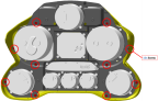
1. Install cluster bezel with 10 #6-32 mounting panel attachment screws with ICA012078 (General Lubricant). Torque the screws in a crisscross pattern and step up to the final torque of 6-10 in-lb.
Note:
Do not over-torque.
Figure 224. Instrument Cluster Bezel
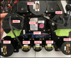
2. Position instrument cluster into aircraft crossbeam rib. Reconnect all electrical connections while holding instrument cluster in place.
a. D9047P to AoA Gauge
b. D9064P to Altimeter
c. D9062P to Artificial Horizon
d. D9056P to Airspeed Indicator
e. D9048P to Tachometer
f. D9049P to Water Temp Gauge
g. D9051P to Oil Pressure Gauge
h. D9050P to Oil Temperature Gauge
i. D9053P to Fuel Gauge
Figure 225. Electrical Connections
Note:
Do not damage pitot-static tubes.
3. Secure instrument cluster to aircraft crossbeam rib with four #8-32 attachment screws. Apply small amount of LOCTITE 222.
4. Attach static tube to the altimeter.
5. Attach static and pitot tubes to airspeed indicator.
6. Re-install hood shell. Slide it forward into the clip hole and then press it down on the instrument cluster.
Verification Method
Turn on master switch, verify the needle position of the Oil Temp, Oil Pressure, Coolant Temp, and Tachometer moved from 6 o’clock position to the lower range of the dial.
Altimeter and airspeed: Perform a pitot-static leak test. (Pitot-Static-AOA
Leak Test Procedures)
Attitude indicator: After turning on the master switch, the instrument should turn on and light up.
Fuel quantity: After turning on the master switch, the instrument should move to indicate the fuel quantity.
AOA: After turning on the master switch, the instrument needle should move to the lower range of the dial.
Perform an annunciator panel inspection. Annunciator
Panel Function
Parent topic