Nose Landing Gear (NLG) Leg Assembly Installation
100427-00
Use the following procedure to install the nose landing gear leg assembly.
Applicable Aircraft Serial Numbers
All
Type of Maintenance
Line
Level of Certification
LSA-RM
Task Specific Training Required
No
Special Tools Required
None
Parts Required
AN7C14A (BOLT, MACH, .439-20, CRES, 1.59375, 0.9375)
ICA007417 (BUSHING, TRUNNION, NLG)
MS21044C7 (NUT, SLFLKG, HEX, CRES, .437-20)
ICA007756 (PIN, WRIST, NLG)
S73HW2-100-043 (RETAINING RING, CRES, .438X0.25)
4040RSS3.125MOD-12 (SPACER, UNTHREADED, CRES, .194X.3125X3.125)
AN526C632-40 (SCREW, MACH, CRES .138-32X2.5)
Z4110-316SS (BINDING POST, CRES, .138-32X.188X1.00)
NAS1149033R (WASHER, FLAT, CRES, .203X.032, PSVT)
Aircraft System and Number
11—Landing Gear
Safety Equipment
As Needed
Consumables
Tef-Gel®
LOCTITE® 222™
Ensure that the NLG leg assembly is complete with leg, trunnion, wrap around bracket, drag link bracket, and wheel centering assembly installed. If the NLG fork steering bearing is not in place, install it before proceeding with the steps below. (Nose Landing Gear Steering Bearing Replacement Procedure)
Task Instructions
1. Locate the NLG leg into position in the NLG box in the aircraft.
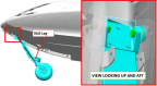
2. Install the AN7C14A bolts through each ear of the NLG trunnion and into the pivot bearings in the NLG box. Use a helper to hold the leg assembly in place.
3. From the inside of the fuselage, install the ICA007417 bushings and MS21044C7 nuts onto the AN7 bolts, the bushings being positioned inside the flanged bearings in the NLG box. Apply Tef-Gel® to the bolt threads.
4. Torque the AN7 pivot bolts and nuts to 322 in-lbf.
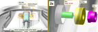
5. Locate the NLG drag link into position in the bracket on the NLG leg and install the ICA007756 wrist pin.
6. Install retaining ring S73HW2-100-043 into the groove in the wrist pin, securing it in place.
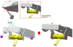
7. Assemble the forward NLG door torsion springs onto the ICA008817 mounts as shown.
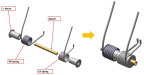
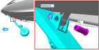
8. Place springs and mounts into position as shown, then slide in the 4040RSS3.125MOD-12 spacer.
9. Apply LOCTITE® 222™ to the threads of the AN526C632-40 screw.
10. Locate the forward NLG door into position so that the pivot holes align, deflecting the springs in the process.
11. Slide the AN526 screw in place, along with Z4110-316SS binding post and its NAS11490332R washer. Torque screw to 8 ± 2 in-lbs.
12. Cycle the nose landing gear. Confirm that the landing gear indicator indicates the correct gear position. Ensure that gear doors do not interfere with any other components when the nose landing gear is fully extended and retracted. Adjust as necessary.
13. Lower the aircraft from jacks or remove weight and foam blocks as appropriate.
Verification Method
The procedure is complete when the nose landing gear leg assembly has been installed and the landing gear cycle checks have been completed successfully.
Parent topic