Nose Landing Gear (NLG) Leg Assembly Removal
100428-00
The following task should be used to remove the nose landing gear (NLG) leg assembly.
Applicable Aircraft Serial Numbers
All
Type of Maintenance
Line
Level of Certification
LSA-RM
Task Specific Training Required
No
Special Tools Required
ICA009749 (WING HARD JACKING POINT)
Parts Required
None
Aircraft System and Number
11—Landing Gear
Safety Equipment
As Needed
Consumables
LOCTITE® 222™
Task Instructions
1. Remove left and right instrument panel top panel. (Right Instrument Panel Top Panel Removal)(Left
Instrument Panel Top Panel Removal)
3. Jack the aircraft up or weight the tail so that the nose gear is clear of the ground (use a safety block under the forward hull if weighting the tail).
4. Use two #2 cross-head drivers to remove the screw and binding post that attach the forward NLG door (these are secured with LOCTITE® 222™).
5. Remove the forward door along with the long spacer, two torsion springs, and two spring mount bushings. The flanged bearings should remain pressed into the wraparound bracket on the NLG leg.
6. Remove the retaining ring and wrist pin from the NLG drag link where it meets the NLG leg bracket, supporting the NLG leg so that it does not over-extend.
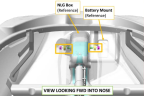
7. Use 5/8 and 11/16 wrenches to remove the two AN7C14A bolts and MS21044C7 nuts that attach the NLG trunnion to the NLG box. For the aircraft right side, the nut is accessed by reaching through the battery box (see below).
Note:
There is a bushing in the bearing on each side of the box.
8. Remove the NLG leg.
Verification Method
The task is completed when the nose landing gear leg has been removed.
Parent topic