Aft Nose Landing Gear (NLG) Door Mechanism Removal, Installation, and Rigging
100436-00
Use these procedures to remove, install, and repair the mechanism for the aft NLG doors.
Applicable Aircraft Serial Numbers
All
Type of Maintenance
Line
Level of Certification
LSA-RM
Task Specific Training Required
No
Special Tools Required
None
Parts Required
See task procedures.
Aircraft System and Number
11—Landing Gear
Safety Equipment
As Needed
Consumables
None
Note:
Carefully inspect each part and any underlying parts or structure for serviceability prior to installation.
Task Instructions
1. Use standard practices to remove and install the components of the Aft Nose Landing Gear Doors and mechanisms that need replacement or repair.
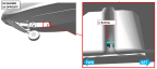
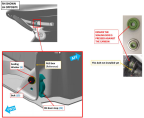
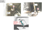
2. Verify Click Bond studs have been installed. The studs are bonded into the NLG box as shown. Repeat this step for both LH and RH sides.
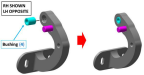
3. Verify that the door bushings have been installed into the forward bellcrank pockets as shown. Repeat this step for both LH and RH sides.
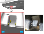
4. Verify that the door bushings have been installed into the aft bellcrank pockets as shown. Repeat this step for both LH and RH sides.
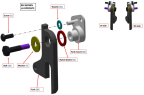
5. Prepare the door forks. Stack up door fork and fork mount with hardware as shown for the RH side. The LH side is a mirror image. Repeat for the LH side.
Qty | Item No | Part No |
|---|---|---|
1 | (1) | 10F50MTT3 |
1 | (6) | 90295A492 |
1 | (7) | 91525A323 |
1 | (16) | AN4C11A |
1 | (20) | ICA010039 |
1 | (22) | ICA010049 |
1 | (31) | NAS1149C0332R |
6. Install the door forks. Install the RH stack-up of hardware from the previous step into the RH side of the NLG box as shown with the specified hardware. Torque to the specification identified. The LH side is a mirror image. Repeat for the LH side.
Qty | Item No | Part No |
|---|---|---|
1 | (29) | MS21043-3 |
1 | (30) | MS21043-4 |
1 | (31) | NAS1149C0332R |
1 | (33) | NAS1149C0432R |
7. Prepare the door stops by installing one helicoil insert into the RH door stop. Repeat for the LH side.
Qty | Item No | Part No |
|---|---|---|
1 | (3) | 3591-3N285 |
1 | (21) | ICA010044 |
1 | (24) | ICA010082 |
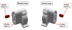
8. Install the door stops from the previous step into the NLG box with the hardware shown. Temporarily leave the hardware loose allowing the door stop to swing freely. Repeat for the LH side.
Qty | Item No | Part No |
|---|---|---|
1 | (5) | 75101 |
1 | (15) | AN3C4A |
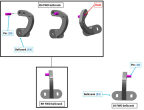
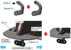
9. Prepare forward RH bellcrank by pressing pin into bellcrank so that the pin is flush with the aft face of the bellcrank. Prepare the forward LH bellcrank so that it is a mirror image of the forward RH bellcrank.
Qty | Item No | Part No |
|---|---|---|
1 | (10) | 97395A485 |
1 | (19) | ICA014424 |
1 | (23) | ICA014425 |
10. Insert bushings into the RH and LH forward bellcranks from the previous step as shown. Install the forward bellcranks into the RH and LH bellcrank pockets as shown using the hardware listed. Torque all hardware as specified.
Note:
Ensure that bolt (14) goes through both the door stop and through the bellcrank.
Qty | Item No | Part No |
|---|---|---|
1 | (4) | ICA014423 |
1 | (5) | 75101 |
1 | (14) | AN3C30A |
1 | (29) | MS21043-3 |
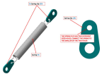
11. Prepare door springs by attaching two spring clips onto the spring. Prepare a total of two of these assemblies—one for the LH and one for the RH.
Note:
Ensure the spring is connected to the smaller of the two holes on the spring clip.
Qty | Item No | Part No |
|---|---|---|
1 | (9) | 9654K196 |
2 | (25) | ICA010385 |
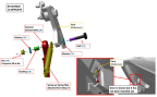
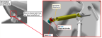
12. Install the door springs and pushrod subassemblies to the door fork. Install one end of the spring/clip assembly from the previous step and the RH threaded rod end of the pushrod assembly onto the RH NLG fork using the hardware shown. Torque to the specified value. Repeat for the mirror-image LG side.
Note:
Orient pushrod subassembly so that the RH threaded rod end is at the top and the LH threaded rod end is at the bottom.
Qty | Item No | Part No |
|---|---|---|
1 | (11) | AN3C10A |
1 | (18) | ICA008887 |
1 | (28) | ME000270 |
1 | (29) | MS21043-3 |
2 | (31) | NAS1149C0332R |
13. Install the pushrod subassembly to the forward bellcrank. Connect the opposite side of the pushrod subassembly to the RH forward bellcrank using the hardware shown. Torque to the specification listed. Repeat for the mirror-image LH side.
Qty | Item No | Part No |
|---|---|---|
1 | (12) | AN3C11A |
1 | (18) | ICA008887 |
1 | (29) | MS21043-3 |
2 | (31) | NAS1149C0332R |
1 | (32) | NAS620C10 |
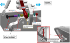
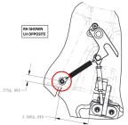
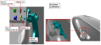
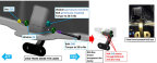
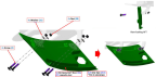
14. Set the pushrod length to the door lock position. Adjust the pushrod so that the fork stop hits the pin (see Point A in image) at the same time as the lower stop hits the pin (see Point B in the image). It may be necessary to keep pressure on the door in the open position so that the lower stop stays in contact with the pin while you adjust the pushrod. Confirm that the door locks in the open position. Torque the jam nuts to 53 in-lbf. Repeat this step for the mirror-image LH side.
15. Install door spring to stud. Ensure that the CB200 applied to the click-bond stud is fully cured. Connect the spring clip to the Click Bond stud and secure with the hardware shown. Torque to the specification show. Repeat for the mirror-image LH side.
Qty | Item No | Part No |
|---|---|---|
1 | (8) | 93013A605 |
1 | (29) | MS21043-3 |
16. Insert bushings into the RH and LH aft bellcranks. Install the aft bellcranks into the RH and LH aft bellcrank pockets as shown using the hardware listed. Torque all hardware as specified.
Qty | Item No | Part No |
|---|---|---|
1 | (4) | 6362K112 |
1 | (23) | ICA010059 |
2 | (5) | 75101 |
1 | (13) | AN3C12A |
1 | (29) | MS21043-3 |
1 | (19) | ICA010035 |
17. Install doors to the bellcranks by loosely installing the RH and LH doors to the bellcranks using the hardware shown.
Qty | Item No | Part No |
|---|---|---|
4 | (2) | 10F87MTT3/50TL |
1 | (26) | ME000851 |
4 | (29) | MS21043-3 |
4 | (31) | NAS1149C0332R |
1 | (27) | ME000853 |
A/N | (203) | 09-31645 |
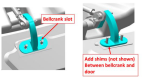
18. Fit the doors to the aircraft per the conditions in the nose landing gear inspection procedure. (Nose Gear Inspection) Make adjustments as necessary using the following adjustment options:
◦ Adjust the position of the door in the bellcrank slot.
◦ Add shims between the bellcranks and the doors with a maximum of four shims installed per bellcrank.
Qty | Item No | Part No |
|---|---|---|
A/N | (201) | ICA010389 |
Verification Method
Inspect the Nose Landing Gear per the inspection procedure. (Nose Gear Inspection)
Operational Check—Extend NLG. Verify doors open fully and are locked into position. Retract NLG. Verify 7.5 amp NLG fuse does not blow and that the NLG doors are closed fully. If fuse does blow, repeat rigging steps until a successful trial.
Parent topic