Parking Brake Valve Assembly and Installation Procedure
100450-00
Use the following procedure to assemble and install the parking brake valve.
Applicable Aircraft Serial Numbers
All
Type of Maintenance
Line
Level of Certification
LSA-RM
Task Specific Training Required
No
Special Tools Required
None
Parts Required
None
Aircraft System and Number
11—Landing Gear
Safety Equipment
As Needed
Consumables
Tef-Gel®
Task Instructions
1. Install parking brake handle on the parking valve using the screw indicated. Apply thread locker to leading screw threads.
Figure 316. Initial Assembly of Parking Valve
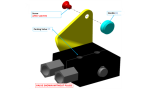
2. Torque screw to 13 in-lb.
3. Remove the plugs from parking valve.
4. Apply a 360° bead of threadlocker to the leading threads of the NPT thread end of the fittings. Install fittings into valve until finger tight.
Figure 317. Final Assembly of Parking Valve
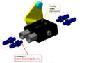
5. Wrench tighten 2-3 full turns from finger tight. DO NOT EXCEED 100 in-lb.
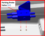
6. Place parking brake valve in its installation location as shown (but do not install bolts).
Figure 318. Orientating the Parking Valve
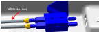
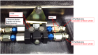
7. Connect AFT brake lines to parking brake valve. Torque fittings to 120-132 in-lbs. Check that hardware is secure.
Figure 319. Installation of Brake Lines onto Parking Valve
8. Connect brake line fittings to parking brake valve and lower adapters on brake master cylinders.
Figure 320. Completed View of Parking Valve
9. Torque 4x FWD brake line fittings (2x at parking brake, 2x at brake master cylinders) to 90-132 in-lb. Check that hardware is secure.
10. Install parking brake using Neoprene washers. Apply Tef-Gel®to bolt threads. Torque 2x bolts to 13-15 in-lb. Check that hardware is secure.
11. Bleed the brakes per the procedure in the Beringer Manual.
Verification Method
Verify that the parking brake valve is fully assembled. Check for correct operation and no leaks.
Parent topic