Balance Propeller
100055-01
Use the following procedure to balance the propeller.
Applicable Aircraft Serial Numbers
All
Type of Maintenance
Line
Level of Certification
LSA-RM
Task Specific Training Required
No
Special Tools Required
Propeller Balance System (such as ProBalancer Sport or DynaVibe GX3)
Parts Required
10F75MTT3-50TL (SCREW, MACH TH, 6LOBE, CRES, 10-32X.750X.500)
10F87M773/50TL (SCREW, MACH TH, 6LOBE, CRES, 10-32X.875)
NAS1149C0316R (WASHER, FLAT, CRES, .188X.016, PSVT)
NAS1149C0332R (WASHER, FLAT, CRES, .203X.032, PSVT)
NAS1149C0363R (WASHER, FLAT, CRES, .188X.063, PSVT)
NASM970C3 (WASHER, FENDER, CRES, .203X.875X.063)
98370A027 (WASHER, FLAT, 18-8SS, .203X.500X.080-.099)
Aircraft System and Number
13—Propulsion
Safety Equipment
As Needed
Consumables
ICA012078 (LUBRICANT, GENERAL PURPOSE) Tef-Gel®
SpeedTape (or equivalent aluminum pressure-sensitive tape)
3M 7610 (TAPE, REFLECTIVE, 3M SCOTCHLITE)
Task Instructions
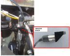
3. Install accelerometer (vibration sensor) onto the gearbox per Propeller Balance System manual. Ensure sensor is secured tightly and oriented vertically. See Figure 424 as an installation example.
Figure 424. Accelerometer Installation Example Using an Existing Fuel Rail Screw (A ProBalancer Sport Accelerometer Shown)
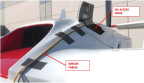
4. Route accelerometer wire through the oil access door in the engine cowl, reinstall the top engine cowl, and connect antennas. (See Figure 425 and Install
Engine Cowlings.)
Figure 425. Accelerometer Wire Routed Through the Oil Access Door
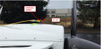
5. Secure the optical tachometer from the Propeller Balance System to the top of the engine cowl with tape about 9 to 12 inches from the propeller. (Figure 426)
Figure 426. Photo Tachometer Location
6. Run the optical tachometer and accelerometer wire together to the front of the aircraft. Secure with SpeedTape. (Figure 425)
7. Connect both sensors to the Propeller Balancer System unit.
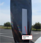
8. Place TAPE, REFLECTIVE on one of the propeller blades on the FWD face of the blade. The tape must be in the line of sight of the photo tachometer. This blade is now identified as Blade 1. (Figure 427)
CAUTION:
Turn propeller only counterclockwise looking FWD.
Note:
Use a ruler to ensure the reflective tape is within the line of sight of the sensor.
Figure 427. Example of Reflective Tape Placement
9. Perform propeller balance using selected Propeller Balance System and its manual. After the system runs the test, it will output a vibration magnitude in inches per second (IPS) and suggest locations for adding weight.
Note:
Engine speed should be 5000-5100 RPM during balancing.
10. Rotate the propeller until the reflective tape is aligned with the photo tachometer.
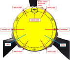
11. AFT looking forward, raise the propeller protractor centered over the spinner. Align the sensor icon with the vibration sensor.
12. Use the protractor and Figure 428 to select one of the six holes that best matches the suggested location for installing washers.
Figure 428. Example of Propeller Protractor Alignment AFT Looking FWD
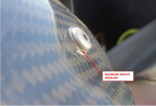
13. Install a combination of washers listed in this task to achieve the suggested weight calculated by the system. No more than three washers should be added to any one location. Apply LUBRICANT to spinner dome screws and torque to 26 in-lbs with a T20 Torx driver. (Figure 429)
Note:
The original screws may be replaced with longer screws, but the additional weight must be accounted for. Ensure there are at least one thread protruding out of the nut plate.
Figure 429. Balancing Weight (Washer) Installed on Spinner Dome
14. Repeat Steps 9 through 13 until the vibration magnitude is less than 0.15 IPS.
15. Remove all sensors, wires, and test equipment from the aircraft. Remove the top engine cowl.
16. Reinstall any screws that may have been used to mount the accelerometer.
Verification Method
Ensure the spinner dome screws are torqued to spec and the vibration magnitude is less than 0.15 IPS.
Parent topic