Bilge Pump Installation
100066-00
Use the following procedure to install the bilge pump.
Applicable Aircraft Serial Numbers
00021+
Type of Maintenance
Line
Level of Certification
LSA-RM
Task Specific Training Required
No
Special Tools Required
None
Parts Required
PUMP, BILGE, 12VDC 1.8A, 550GPH
TY24MX CABLE-TIE, NYLON 6-6, 30LBS, 5.50, TY-RAP
16-120-0340W HOSE, SHIELDS BILGEFLEX, .75, WHITE
3806 CLAMP, WORM DRIVE, MINI, .312X0.781
Aircraft System and Number
03—Electrical System
Safety Equipment
As Needed
Consumables
3M FIRE BARRIER SILICONE SEALANT 2000+B
SILICONE ELASTOMER, ONE-COMPONENT
Task Instructions
1. Clean the bilge area of any sand, stones, or other debris.
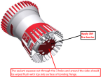
2. Remove the lower screen from the bilge pump and set it aside.
Note:
It will not be used unless the strainer in the aircraft is damaged. To bond in a new lower screen of the bilge pump, use 3M fire barrier (201). Wipe excess sealant extruded from pin holes flush with top side surface of bonding flange. Allow fire barrier to cure for 90 minutes before reinstalling the bilge pump.
Figure 49. Apply 3M Fire Barrier
3. Install the pump body onto the bottom strainer already in the aircraft by aligning it and rotating it clockwise until locked.
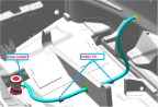
4. Cut hose to 42.0”±1.0”, make cut in the center of the flat section. Attach the bilge pump hose to the pump barb fitting and secure with a 3806 CLAMP as shown below. Route the hose as indicated below. Slide one end of the hose onto the bulkhead fitting in the fuselage wall (until flush with the fuselage wall) and the other end onto the bilge pump (until flush with the bilge pump).
Figure 50. Secure Bilge Pump Hose
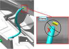
5. For the clamp on the bulkhead fitting in the pilot side fuselage skin, clock the clamp such that the screw housing is fully within the following approximate zone, make sure there is a minimum clearance of .125” from the fuselage roll control cable. Tighten clamps until a seal is achieved.
Figure 51. Clamp Orientation
6. Connect D9009J connector on bilge pump to D9009P connector on main wire harness.
7. Test that the bilge pump operates normally.
Verification Method
The procedure is complete when the fuel tank is installed.
Parent topic