Install Fuel Tank Assembly
100343-01
Use the following procedure to install the fuel tank.
Applicable Aircraft Serial Numbers
00021+
Type of Maintenance
Line
Level of Certification
LSA-RM
Task Specific Training Required
No
Special Tools Required
None
Parts Required
15300010 (CLAMP, HOSE, CRIMP, CRES, OETIKER, 0.344)
TY528MX (CABLE TIE, NYLON 6-6, 50LB, 14.2, TY-RAP)
TY24MX (CABLE TIE, NYLON 6-6, 30LB, 5.50, TY-RAP)
Aircraft System and Number
07—Fuel System
Safety Equipment
As Needed
Consumables
Tef-Gel®
LOCTITE 243
Figure 151. Fuel Tank Installation
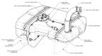
Task Instructions
1. Confirm isolation strip is installed. If not, Install Isolation Strip on Fuel Tank Support If isolation strip is installed, proceed to Step 2.
Figure 152. Fuel Tank Strap Installation
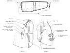
3. Install the fuel tank subassembly into the aircraft fuel tank support structure.
4. Attach the fuel tank strap subassemblies to AFT end of fuel tank support brackets using LUBRICANT and hardware. Figure 152 (Detail D.) Torque bolts to 26 in-lb.
5. Loosely secure the forward ends of the fuel tank straps to the fuel tank brackets using LUBRICANT and hardware. Figure 152 (Detail A.)
6. Adjust isolation channels on the fuel tank straps to ensure that the fuel tank strap will not contact the fuel tank surface after the straps are tensioned. Torque nuts to 10-13 in-lbs.
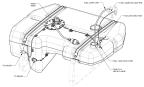
7. Route fuel sump hose through bottom end of fuel filler neck and connect the fuel sump hose to sump hose adapter using a new CLAMP, HOSE, CRIMP (Oetiker clamp). Tighten with ear-clamp crimpers. Figure 153
Figure 153. Fuel Sump Line and Electrical Connections
8. Install the bottom end of the filler neck onto the fuel tank opening flange so that there is a .2”±.1” gap between the bottom face of the filler neck and the top face of the fuel tank. Attach the top end of the filler neck onto the fuel cap adapter. Figure 154
Figure 154. Fuel Filler Neck Install and Electrical Connections
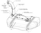
9. Secure both ends of the fuel filler neck using worm drive clamps. Figure 154 Position the bottom hose clamp so that there is a .4”±.1” gap between the bottom edge of the hose clamp and the top face of the fuel tank.
10. Torque both clamps to 18-20 in-lb.
11. Connect fuel cell vent hose to hose barb in fuel cap adapter using the mini worm drive clamp. Figure 154 Torque to 10-13 in-lb.
12. Connect fuel return line to the elbow fuel return port in the tank and torque to 110-130 in-lb with a 11/16 wrench. Figure 154
13. Connect fuel line from fuel pump to coarse fuel filter. Torque fittings to 110-130 in-lb with a 11/16 wrench.
14. Secure T9027 ring terminal from ground wire on fuel tank subassembly to the filler cap adapter using #6-32 cap screw. Torque screw to 9 in-lb. Figure 154
15. Secure fuel filler neck, ground wire, and fuel vent hose with CABLE TIE, NYLON 6-6, 50 LB. Figure 154
CAUTION:
Do not over tension cable tie and create a blockage or kink in fuel vent hose.
18. Connect T9028 ring terminal from fuselage wire harness to bolt and washer on fuel level sensor.
b. Apply LOCTITE 243 to bolt threads and install T9028 ring terminal beneath the washer.
c. Torque bolt to 40-45 in-lb.
19. Secure T9028 ring terminal wire harness and fuel level sensor wire harness to fuel tank with three CABLE-TIE, NYLON 6-6, 30LB.
20. Fill the tank with fuel and check for leaks.
21. Run the engine and check for line leaks.
Verification Method
Complete the Engine Test Run and check for leaks. (Engine
Test Run)
Parent topic