Rigging Pitch Controls
100138-00
Use the following procedure for elevator rigging.
Applicable Aircraft Serial Numbers
All
Type of Maintenance
Line
Level of Certification
A&P
Task Specific Training Required
No
Special Tools Required
Aircraft Cable Tensiometer
Parts Required
As needed based upon inspections and condition of parts. Contact ICON Aircraft for assistance as needed. A list of part numbers in the elevator cable system is below.
Number | Name | Quantity |
|---|---|---|
ICA002203 | SECTOR ASSY, PITCH, AFT | 1 |
ICA002491 | CONTROL CABLE, PITCH, FWD-UPR | 1 |
ICA002495 | CONTROL CABLE, PITCH, FWD-LWR | 1 |
ICA002504 | CONTROL CABLE, PITCH, AFT-UPR | 1 |
ICA002508 | CONTROL CABLE, PITCH, AFT-LWR | 1 |
ICA008756 | BRACKET ASSY, PITCH SECTOR | 1 |
NAS77C4-005 | BUSHING, FLNGD, UNLINED, CRES, .250X.050 | 2 |
ICA009226 | BUSHING, FLANGED, .250X.085X.032 | 2 |
MS20392-1R41 | PIN, STR, HEADED, DRILLED SHK, CRES, .125X1.281 | 1 |
MS20392-1R43 | PIN, STRAIGHT, HEADED, DRILLED SHANK | 1 |
MS21043-4 | NUT, SLFLKG, RDC HEX, CRES, .250-28 | 2 |
MS21251-B5L | TURNBUCKLE BODY, CLIP LKG, BRASS, .156X.250-28X4.00 | 2 |
MS24566-4B | PULLEY, CONT, AFB, .188X3.01 | 4 |
MS24665-151 | PIN, COTTER, CRES, .063X.500 | 2 |
MS24665-153 | PIN, COTTER, CRES, .063X.750 | 8 |
ICA002195 | SECTOR, PITCH, FWD | 1 |
ICA009551 | DOWEL, PITCH SECTOR STOP | 2 |
ICA009472 | PLATE, ANTI ROT FLG, PITCH SECTOR STOP | 2 |
WS-50-S16 | RETAINING RING, EXT SPIRAL, 316 SST, .467X.045 | 2 |
AN3C10A | BOLT, MACH, CRES, 10-32X.625 | 2 |
ICA012054 | PUSHROD, ELEVATOR | 1 |
91630A472 | INSERT, HELICAL, SCREW LOCK, 18-8 SST, 10-32X.380 | 2 |
MS21256-2 | CLIP, LKG, TRNBKL, 1.955 | 4 |
MS20995C20 | WIRE, SAFETY, CRES, .020 | 1 |
ICA012237 | BEARING, SLEEVE, NYLON, .625X.500X.750 | 4 |
Aircraft System
06—Flight Controls
Safety Equipment
As Needed
Consumables
None
Task Instructions
1. Remove water rudder access panel and AFT bulkhead baggage panel. (Removal
and Installation of Inspection Panels and Fairings) (Baggage Sidewall Panel Removal)
2. Remove left hand and right hand forward and main cockpit floor boards.(Remove
Cockpit Floorboard)
5. Remove center console bucket and throttle bezel. (Center
Console Bucket Removal)(Throttle
Handle and Bezel Removal) Retain all fastening hardware.
7. Inspect all components within the pitch circuit for excessive wear. Any components that show excessive wear or damage must be replaced with new components.
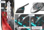
Figure 111. Pitch System Rig Pins
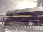
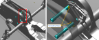
10. Use a tensiometer at least 8 in away from turnbuckles to rig both the upper pitch control cable and lower pitch control cable (cable thickness = 1/8 in). Adjust turnbuckles as required to set cable tension to 20 – 35 lbs. Refer to Figure 112. Operate tensiometer per its manufacturer’s instructions.
Figure 112. Pitch Circuit Tensioning
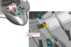
Figure 113. Locking Clip Locations
13. Install horizontal tail and removable HT tips. (Horizontal Tail Removal and Installation)(Horizontal Tail Tip Pin)
14. Ensure the rig pin in the FWD pitch sector is still installed.
15. If installed, remove the hardware which secures the elevator push rod to the elevator control horn. Figure 114
Figure 114. Control Horn Hardware Installation
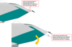
16. Place the digital protractor on top of the elevator and zero the digital protractor while the elevator is in its neutral position, the trailing edge of the elevator should align with the HT tips.
17. After setting the zero position of the elevator, lower the elevator into the -2° position.
18. Adjust the rod end as necessary so that the rod end lines up with the elevator control horn while the elevator is in the -2° position. This will be the initial adjustment. If necessary, final adjustments will be made at a later step if required. Figure 115
Figure 115. Elevator Rigging
19. Temporarily install the hardware which secures the elevator push rod to the elevator control horn. Figure 114
21. Using the digital protractor, check the maximum upward and downward deflection of the elevator. If required, adjust the elevator push tube rod end as necessary to achieve the following:
a. 19° ± 1° upward deflection
b. 21° ± 2° downward deflection
22. Check the FWD and AFT pitch secondary stop:
a. Apply 16±2 lb at the center of the control stick grip. Force should be applied FWD and AFT.
b. Verify that contact is made with the secondary pitch stops (located in keel, below center console) at the specified force.
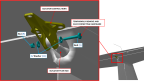
c. Verifying that the primary pitch stops (located in vertical tail) contacts prior to the secondary stops. Figure 116
23. Adjust the bolt on the secondary stops as needed to achieve contact when specified force is applied. Figure 116 If the secondary stops get contacted before the primary stops, not achieving the elevator travel limits, it is acceptable to remove the bolt on the bottom secondary stop.
Figure 116. Secondary Stops Location
24. Once the requirements for the upward and downward deflections have been met, install the hardware to connect the pushrod to the elevator control horn. Torque the pushrod jam nut to 60 in-lbs. Torque the bolt to 20 in-lbs.
25. Ensure that there is no rubbing, binding, or any signs of interference while the elevator is moved throughout its entire range of motion.
27. Install center console bucket and throttle bezel. (Center
Console Bucket Installation)(Throttle
Handle and Bezel Installation)
31. Install left hand and right hand forward and main cockpit floor boards. (Install
Cockpit Floorboard)
Verification Method
Conduct the Check Elevator Rigging Procedure to verify proper rigging. (Inspect
Pitch Rigging)
Parent topic