Throttle Handle and Bezel Installation
100611-01
Use the following procedure to remove the throttle handle and bezel.
Applicable Aircraft Serial Numbers
All
Type of Maintenance
Line
Level of Certification
LSA-RM
Task Specific Training Required
No
Special Tools
No
Parts Required
ME000556 (PAINTED, HANDLES, THROTTLE)
ME000357 (BEZEL, THROTTLE, SUBASSY)
Aircraft System and Number
05—Equipment and Furnishing
Safety Equipment
As Needed
Consumables
LOCTITE®243™
Task Instructions
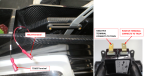
a. Connect T9114 terminal on fuselage wiring harness to the positive terminal (+) on hour meter.
b. Connect T9105 terminal on fuselage wiring harness to the negative terminal (-) on hour meter.
Figure 69. Throttle Bezel Electrical Connections
2. Install throttle bezel. Slide bezel tabs under radio stack bezel and push bezel into place. Figure 68
4. Insert left and right throttle handles. Install 2X Screws which secure throttle handles. Apply LOCTITE® 243™ and torque to 7-9 in-lbs. Figure 66
Verification Method
Procedure is complete when the throttle handle and bezel is installed.
Parent topic