Rigging Yaw Controls
100556-00
Use the following procedure for rudder rigging.
Applicable Aircraft Serial Numbers
All
Type of Maintenance
Line
Level of Certification
A&P
Task Specific Training Required
No
Special Tools Required
Aircraft Cable Tensiometer
Parts Required
As needed based upon inspections and condition of parts. Contact ICON Aircraft for assistance as needed. A list of part numbers in the rudder cable system is below.
Number | Name | Quantity |
|---|---|---|
ICA001941 | WASHER, PLAIN, CRES,.250X.875X.120 | 1 |
ICA002125 | SPACER, WATER RUDDER BELLCRANK | 1 |
ICA002388 | CONTROL CABLE, RUDDER | 2 |
ICA002392 | BELLCRANK WELDMENT,WATER RUDDER | 1 |
ICA007023 | BELLCRANK WELDMENT, RUDDER | 1 |
ICA007292 | BELLCRANK, INTERCONNECT, RUDDER PEDAL | 2 |
ICA007938 | BEARING BLOCK, TORQUE TUBE, RUDDER | 1 |
ICA007939 | PIN, BEARING, TORQUE TUBE, RUDDER | 1 |
ICA009269 | BUSHING, FLANGED, .250X.438X.102X.063 | 1 |
ICA009484 | HOUSING, BEARING, YAW TORQUE TUBE | 4 |
ICA009488 | TORQUE TUBE WELDMENT, YAW, AFT | 1 |
ICA009490 | CONTROL CABLE, YAW, FUSLG, CNTR-LH SIDE | 1 |
ICA009492 | CONTROL CABLE, YAW, FUSLG, CNTR-RH SIDE | 1 |
ICA009493 | BEARING SUPPORT, YAW TORQUE TUBE, UPR | 4 |
ICA009498 | CENTERING SPRING ASSY, 11LB/IN | 1 |
ICA009503 | STOP, YAW SECTOR | 2 |
ICA009519 | TORQUE TUBE WELDMENT, YAW, FWD | 1 |
ICA009521 | BUSHING, PLAIN, NITRONIC, .191X.280X.500 | 1 |
ICA010413 | ROD END, BBRG, EXT THD, .190-32X_.188, RADIAL GROOVE | 2 |
ICA012055 | PUSHROD, RUDDER | 1 |
ICA012239 | CLIP, LOCKING, TURNBUCKLE, LONG, .042 WIRE | 2 |
1191-3CN380 | INSERT, HELICAL COIL, CRES, 10-32X.380 | 2 |
92778A121 | SET SCREW, HEX, SST, 10-32X.5 | 2 |
93013A330 | SPACER, AL, .250X.500X.500, BLACK | 1 |
9852 | RADIAL SHAFT SEAL | 1 |
AS3582-030 | O-RING, VQM (SILICONE), 1.614X.070 | 1 |
CN609CR3P | NUT PLATE, TWO LUG, ADH BND, .190-32 | 12 |
CN609CR4P | NUT PLATE, TWO LUG, ADH BND, .250-28 | 1 |
MS20392-1R23 | PIN, STR, HEADED, DRILLED SHK, CRES, .125X.719 | 2 |
MS21151-7C | ROD END, BBRG, MALE, 10-32, SLOTTED | 2 |
MS21251-A3S | TURNBUCKLE BODY, CLIP LKG, AL, .093X.190-32X2.25 | 2 |
MS21251-B5L | TURNBUCKLE BODY, CLIP LKG, BRASS, .156X.250-28X4.00 | 2 |
MS21256-1 | CLIP, LKG, TRNBKL, 1.078 | 4 |
MS21256-2 | CLIP, LKG, TRNBKL, 1.955 | 10 |
MS24566-3B | PULLEY, CONT, AFB, .188X1.51 | 2 |
MS24665-151 | PIN, COTTER, CRES, .063X.500 | 2 |
MS27641-4 | BEARING, BALL, AFR AFB, INTMD DUTY, .250X.750X.281 | 2 |
MS27641-8 | BEARING, BALL, AFR AFB, INTMD DUTY, .500X1.125X.375 | 4 |
MS27646-41 | BEARING, BALL, AFR AFB, EX LD, 1.06X1.50X.281 | 1 |
NAS428H3-7 | BOLT, MACH-CRWND HEX HD, ADJUSTING, CRES, 10-32X.875 | 2 |
NAS75C4-006 | BUSHING , PLAIN, CRES, .250X.375X.188 | 1 |
NAS77C3-015 | BUSHING, FLNGD, UNLINED, CRES, .190X.150 | 2 |
VH-112-S16 | RETAINING RING, PLAIN, LIGHT DUTY, 316SS, 1.25X.025 | 4 |
VS-50-S16 | RETAINING RING, PLAIN EXTERNAL, LIGHT DUTY, 316SS, .500X.022 | 4 |
Aircraft System
06—Flight Controls
Safety Equipment
As Needed
Consumables
LOCTITE® 243™
Task Instructions
1. Remove AFT Tail Access Panel, Water Rudder Access Panel, and AFT Bulkhead Baggage Panel. (Removal
and Installation of Inspection Panels and Fairings) (Baggage Floor Removal)
4. Remove Seat Back and Seat Pan. (Remove Seat Back) (Seat Pan Removal) Retain all fastening hardware.
6. Remove Seatbelt Reel Cover, left hand and right hand baggage sidewalls, and baggage headliner. (Seat Belt Inertia Reel Removal)(Baggage Sidewall Panel Removal Baggage Sidewall Panel Removal) (Headliner Removal)
7. (Optional) Remove fuel tank if needed. (Remove Fuel Bladder orRemove
Fuel Tank Assembly) Retain all fastening hardware.
8. Remove Center Console Bucket and Throttle Bezel. (Center
Console Bucket Removal)(Throttle
Handle and Bezel Removal) Retain all fastening hardware.
9. Inspect all components within the rudder circuit for excessive wear. Any components that show excessive wear or damage must be replaced with new components.
Figure 133. Rudder Return Spring
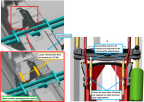
11. Install two .375 in diameter rig pins through the keel in the Yaw Torque Tube Rig Pin holes.
Note:
Ensure rig pin extends the entire width of the keel, through both holes in the keel.
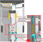
Figure 134. Yaw Torque Tube Rig Pin Locations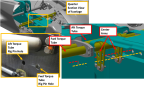
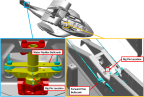
Figure 135. FWD Yaw Bellcrank and Water Rudder Rig Pin Locations
12. Use a tensiometer (cable thickness = 3/32 in) to rig both middle yaw control cables. To achieve the following, refer to Figure 136:
a. Adjust inner set of turnbuckles to set cable tension on both cables to 5-12 lbs
b. Ensure 1 to 12 rod end threads are exposed after turnbuckle adjustment
c. Ensure that no more than 3 cable terminal threads are exposed after turnbuckle adjustments
d. Ensure that water rudder remains centered 0° ± .5° relative to the BL_0 plane after rigging is complete
Figure 136. Middle Yaw Circuit
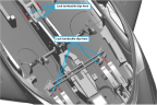
13. Use a tensiometer to rig both AFT Yaw Control Cables (cable thickness = 1/8 in). Refer to the tensiometer manufacturers’ calibration card to correctly read cable tension for the cable diameter measured. To achieve the following, refer to Figure 137:
a. Adjust outer set of turnbuckles to set cable tension on both cables to 18-22 lbs
b. Ensure 1 to 16 rod end threads are exposed after turnbuckle adjustment
c. Ensure that no more than 3 cable terminal threads are exposed after turnbuckle adjustments
d. Ensure that water rudder remains centered 0° ± .5° relative to the BL_0 plane after rigging is completed
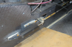
Figure 137. AFT Yaw Circuit Tensioning
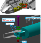
14. Install the forward end of centering spring onto the LH side of the keel using LOCTITE® 243™ and the noted hardware. Torque hardware to 10-13 in-lbs. Figure 138
Figure 138. Centering Spring Install
a. 4 total on aft section of Yaw System – 2X ICA012239 (Rod End), 2X MS21256-2 (Wire Terminal)
b. 4 total on mid section of Yaw System – 4X MS21256-1
c. 8 total on Rudder Pedal Control Cables – 8X MS21256-2
Figure 139. Turnbuckle Location
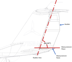
16. Position the rudder rigging template (ICA013055) or a protractor as shown in Figure 140, Center the 0° indication of the rigging template or protractor with respect to the center of the tail section under the rudder.
Figure 140. Rudder Measurement Plane
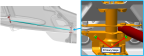
17. Adjust rudder push tube length to set the neutral position of the rudder to be 1°+/-1° trailing edge right. This must be done by removing the AN3C7A bolt that secures the FWD side of the push rod and adjusting the rod end. Figure 141
Figure 141. Rudder Push Tube Adjustment
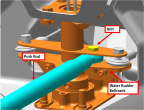
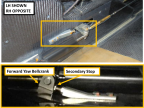
Figure 142. Secondary Stop Adjustment
19. Remove all rig pins from the Yaw System:
a. 2X rig pins from Yaw Torque Tubes
b. Rig pin from FWD Yaw Bellcrank
c. Rig pin from AFT Water Rudder Bellcrank
20. Verify that Yaw System components do not contact surrounding carbon surfaces or components during operation.
21. Verify that the rudder neutral position is still within the limits specified. Adjust if necessary. Torque push tube jam nuts to 40 in-lbs. Torque through bolts that secure the push tube to 26 in-lbs.
22. With the aid of another person, check the rudder maximum travel limits. Have a helper push each rudder pedal against the stop (stop contacts at water rudder bellcrank should be heard). While holding very light (1-2 lbf) pressure towards neutral on the rudder trailing edge to remove play.
a. Trailing Edge Left: 11°+/-1°
b. Trailing Edge Right: 14°+/-1°
Figure 143. Primary Stop Locations
24. With the aid of another person, adjust the secondary stops, torque to 12-15 in-lbs. Do not exceed 25 in-lbs. Depress the RH pedal until the primary stop is contacted. Adjust the gap between the secondary stop and bellcrank to 0.032-0.036 in. Figure 142
25. Repeat step 17 for the LH pedal.
26. Install AFT Tail Access Panel, Water Rudder Access Panel, and AFT Bulkhead Baggage Panel. (Removal
and Installation of Inspection Panels and Fairings)(Baggage Floor Installation)
27. Install left hand and right hand forward and Main Cockpit Floor Boards. (Install
Cockpit Floorboard)
30. Install Seatbelt Reel Cover, left hand and right hand baggage sidewalls, and Baggage Headliner. (Seat Belt Inertia Reel Installation)(Baggage Sidewall Panel Installation Baggage Sidewall Panel Installation)(Headliner Installation)
32. Install Center Console Bucket and Throttle Bezel. (Center
Console Bucket Installation)(Throttle
Handle and Bezel Installation)
Verification Method
Conduct the Check Rudder Rigging procedure (Inspect Yaw Rigging) to verify proper rigging.
Parent topic