Inspect Yaw Cable Tension
100553-00
This section contains instructions to check rudder cables for correction tensions.
Applicable Aircraft Serial Numbers
All
Type of Maintenance
Line
Level of Certification
LSA-RM
Task Specific Training Required
No
Special Tools Required
None
Parts Required
None
Aircraft System and Number
06—Flight Controls
Safety Equipment
As Needed
Consumables
None
Task Instructions
1. Remove AFT Bulkhead Baggage Panel. (Baggage Sidewall Panel Removal) Retain all fastening hardware.
2. Remove the Water Access Panel. (Removal
and Installation of Inspection Panels and Fairings) Retain all fastening hardware.
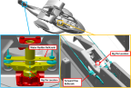
4. Install two .1875 in diameter rig pins, one in FWD Yaw Bellcrank and one in the Water Rudder Bellcrank. Figure 129
Figure 129. FWD Yaw Bellcrank and Water Rudder Rig Pin Locations
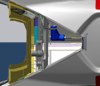
5. From within the AFT Bulkhead Baggage Access Window, use a tensiometer (cable thickness = 1/8 in) to measure rudder cable tension. Refer to Figure 130. Ensure they all are within 18-22 lbf of tension. Refer to the manufacturers’ calibration card to correctly read cable tension for the cable diameter.
Figure 130. Rudder Cable Tension Check Location. View is looking down from within the access hole.
6. Remove all installed rig pins:
a. Water Rudder Bellcrank Rig Pin.
b. FWD Yaw Bellcrank Rig Pin.
7. Install Center Console Bucket using retained hardware during removal. (Center
Console Bucket Installation)
8. Install the Water Rudder Access Panel using retained hardware during removal. (Removal
and Installation of Inspection Panels and Fairings)
9. Install AFT Bulkhead Baggage Panel using retained hardware during removal. (Baggage Sidewall Panel Installation)
Verification Method
Record results and check against requirement. If requirement is not met complete rudder rigging. (Inspect Yaw Rigging)
Parent topic