Inspect Yaw Rigging
100111-00
The following section contains the information required to perform the A5 maintenance inspection on the rudder.
Applicable Aircraft Serial Numbers
All
Type of Maintenance
Line
Level of Certification
LSA-RM
Task Specific Training Required
No
Special Tools Required
ICA013055—Rudder Deflection Template
Parts Required
None
Aircraft System and Number
06—Flight Controls
Safety Equipment
As Needed
Consumables
None
Task Instructions
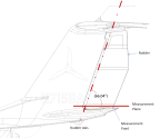
1. Position the rudder rigging template (ICA013055) or a protractor as shown in Figure 131, Center the 0° indication of the rigging template or protractor with respect to the center of the tail section under the rudder.
2. Swing the rudder surface back and forth by hand and verify it returns to a repeatable neutral position. Record neutral deflection. The neutral position of the rudder should be 1°+/-1° trailing edge right.
Figure 131. Rudder Measurement Plane
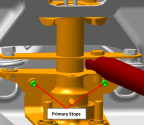
3. With the aid of another person, check the rudder maximum travel limits. Have a helper push each rudder pedal against the stop (stop contacts at water rudder bellcrank should be heard). While holding very light (1-2 lbf) pressure towards neutral on the rudder trailing edge to remove play.
a. Trailing Edge Left: 11°+/-1°
b. Trailing Edge Right: 14°+/-1°
Figure 132. Primary Stop Locations
Verification Method
Record results and check against requirements.
Parent topic