Coolant Overflow Bottle Installation
100113-01
Use the following procedure to install the coolant overflow bottle.
Applicable Aircraft Serial Numbers
All
Type of Maintenance
Line
Level of Certification
LSA-RM
Task Specific Training Required
No
Special Tools Required
None
Parts Required
CB9120V5 (CABLE TIE)
922327 (COOLANT OVERFLOW BOTTLE)
AN316C49 (NUT)
51135K21 (SILICONE TUBING)
TY24MX (CABLE TIE)
552K25 (TYGON TUBING)
3804 (HOSE CLAMP)
Aircraft System and Number
13—Propulsion
Safety Equipment
As Needed
Consumables
LOCTITE® 603
LOCTITE®243™
Task Instructions
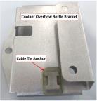
1. If installing a new coolant overflow bottle bracket, prepare it as follows:
b. Lightly abrade the bonding area of the bracket and clean with isopropyl alcohol.
c. Bond the anchor to the bracket with Click Bond CB200 adhesive as shown. Allow to cure for 2 hours.
Figure 394. Coolant Overflow Bottle
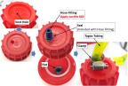
2. If installing a new 922327 coolant overflow bottle, prepare it as follows:
a. Unscrew the cap from the bottle and drill the existing vent hole out to 6mm (.236 in) diameter.
b. Apply LOCTITE®603 to the threads of a 5058K34 hose fitting. Insert the hose fitting with its seal into the vent hole as shown in Figure 395.
c. Secure the hose fitting using an AN316C49 nut torqued to 44 in-lbf
d. Reinstall cap on bottle.
Figure 395. Coolant Overflow Bottle
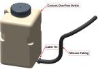
3. If installing new hoses, prepare them as follows:
a. Cut a 10-inch length of 51135K21 silicone tubing and attach it to the bottom nipple of the bottle. Secure with a TY24MX cable tie as shown in Figure 396.
b. Cut a 42-inch length of 552K25 Tygon tubing and install tubing on the bottle cap hose fitting using a 3804 hose clamp.
Figure 396. Coolant Overflow Bottle
4. Install the coolant overflow bottle bracket on the engine as shown in Figure 397. using the noted hardware. Apply LOCTITE® 243™ to the screw threads.
Figure 397. Coolant Overflow Bottle
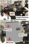
5. Torque the two M8 bolts to 17.7 ft-lbf (212 in-lbf). Torque the M10 bolt to 25.8 ft-lbf (310 in-lbf).
6. Install the coolant overflow bottle on the bracket using two TY29MX cable ties as shown in Figure 398. Orient the bottle with black silicone hose facing forward (away from propeller flange).
a. Attach the black silicone hose to the nipple on the expansion tank and secure using a Ty24MX cable tie.
b. Route the yellow Tygon hose down through the bracket and secure to the bracket’s anchor using a TY24MX cable tie. Ensure that the cable tie does not pinch hose.
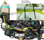
c. Secure the Tygon tubing to the engine mount as shown in shown in Figure 399 using three TY23MX cable ties. The cable ties should be spaced 1-2 inches apart and tightened until tubing width measures .250-.313 as shown. Before tightening the cable ties, ensure that the tubing does not have enough slack to contact any rotating hardware such as the cooling fan or prop flange.
d. Direct the free end of the Tygon hose to the bottom of the firewall near the low point drain.
Figure 398. Coolant Overflow Bottle
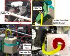
Figure 399. Coolant Overflow Bottle
8. Fill the overflow bottle to the mid-range level with new coolant. (Approved Engine Coolant Grades and Capacity)
Verification Method
Procedure is complete when steps are finished.
Parent topic