Transponder and ELT Antenna Replacement
100141-01
Use the following task to replace the ELT transponder and transmitter antennas. For Removing and Installing the VHF Comm Transceiver and Transponder see Remove VHF Comm Transceiver and Transponder and Install VHF Comm Transceiver and Transponder.
Applicable Aircraft Serial Numbers
All
Type of Maintenance
Line
Level of Certification
LSA-RM
Task Specific Training Required
No
Special Tools Required
None
Parts Required
ICA012199 (ANTENNA, ELT)
ICA012182/ICA009540 ELT ANTENNA GROUND
00745-00-01 (TRANSPONDER UNIT TT22)
AV-74 (ANTENNA, TRANSPONDER)
For ASN 00139+
ICA015003 (WASHER, ELECTRICAL-INSULATING, .500 ID, .625 OD, .028-.034)
ICA015004 (WASHER, ELECTRICAL-INSULATING, .500 ID, .750 OD, .014-.016)
Aircraft System and Number
10—Instruments (and Avionics)
Safety Equipment
As Needed
Consumables
TT-I-735A, or equivalent (ISOPROPYL ALCOHOL)
Silicone Rubber Sheet (0.25” Thick)
Aluminum Foil Tape (3M 425)
CB200 2-Part Acrylic Adhesive
Reference SAFO 17002 as needed while performing transponder and VHF maintenance tasks.
Figure 235. Transponder and ELT Antenna Replacement for ASN 00001-00138
Figure 236. Transponder and ELT Antenna Placement for ASN 00139+
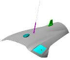
Note:
On the 000139+ configuration the Transponder Antenna has moved from the FWD position to the AFT position. All instructions remain the same.
Task Instructions
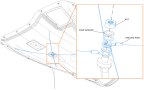
2. Carefully remove the nut and star washer. A new nut and washer is supplied with the new ACK Whip Antenna.
3. Carefully remove the ELT antenna.
Figure 237. Remove ELT ANTENNA
4. Carefully clean the four ELT grounding rings and wires with isopropyl alcohol.
5. If needed, replace grounding rings and/or wires. Dis-bond and remove adhesive. If not needed, skip to step 12.
Note:
All substrate materials must be protected from excessive temperatures exceeding 200° F during the application of heat to soften the adhesive material attaching to the fastener. Excessive temperatures can cause dis-bond, delamination, and blistering of composite substrates, resulting in a loss of strength and reliability.
Note:
Keep the maximum output air temperature of the heat gun below the threshold of damage temperature of the substrate and any surrounding components.
Note:
Use any available technologies to (infrared, temperature sensitive paint, etc.) monitor the temperature of the nearby substrate during the operation. It should always be below the threshold temperature.
Note:
Mask adjacent components and substrates with thermal barrier (silicone sheet) to minimize heat transfer to unintended areas.
CB200 Dis-bond Instructions
6. Cut a conformal mask from silicone rubber sheet (0.25” thick) with the following features:
a. The mask should extend a minimum of three inches beyond the original adhesive dollop securing the ELT grounding wires, in all directions.
b. In the middle of the mask, minimally cut a suitably sized hole to permit penetration of the original adhesive dollop intended to be heated and removed.
c. Drape the mask over the adhesive dollop and secure and Aluminum Foil Tape (3M 425).
7. Use a heat gun tool to heat the bond for removal. Hold the heat gun at a 90° inclination to the bond (i.e., perpendicular to the adhesion surface), and position it approximately one inch from the ground wire on the bottom of the cowl. Center the airstream onto the adhesive dollop.
8. Allow the heat gun to dwell above the adhesive dollop for 20-30 seconds, initially, and then additional 10 second increments as needed. The adhesive will soften adequately so that the ELT ground wires can be carefully released from the bonded area.
9. Using the same methods, heat the remaining adhesive dollops securing the ELT ground wires.
10. Use a scraper to remove all the adhesive material. Be careful not to damage cowling or ELT ground wires during this operation.
11. Following removal of the ELT ground wires, inspect cowling for damage. Contact ICON Aircraft if any anomalies are found.
Note:
ASN 00001-00138 originally did not have insulated washers installed. They must be installed by preparing the ACK ELT Whip Antenna hole. Step 12 applies only to ASN 00001-00138 ONLY.
Installation
12. ASN 00001-00138 ONLY. Change the ELT hole size by drilling a .635+.015/-.009. Deburr the hole as necessary taking care not to break hole edges more than .010”.
13. Using isopropyl alcohol, clean the area around the mounting hole on the outside painted surface and on the inside unpainted surface of the upper engine cowling.
14. Insert the BNC connector of the new ACK ELT Whip Antenna into the mounting hole.
15. Clean the threads of the BNC connector with isopropyl alcohol.
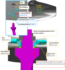
16. Secure the ACK ELT Antenna and ground wires:
a. Install insulting washers ICA015003 (FN003) and ICA015004 (FN002) and ELT ground wires (four terminals) on lower unpainted side of cowl and secure using star washer and nut. (Figure 238)
b. Ensure that each ring terminal is at a 90° angle from one another.
Figure 238. Installation of ACK ELT Whip Antenna
17. Torque the nut on the BNC connector to 13-15 in-lbs. Ensure the ground wire terminals do not rotate.
18. Verify the wires do not exit the connector at sharp angles.
19. Verify the wires are not stressed (exhibit no freedom of movement).
20. Verify the wires are not pinched at connection points or edges near installation.
Figure 239. Bottom of Cowling, Bonding Locations
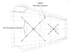
22. Prepare the CB200 in accordance with the manufacturer’s instructions. Note the application time, handling time, and cure time.
23. Apply 8x 0.50” diameter dollops of CB200 at the bonding locations.
24. On the top, painted, side of the cowling verify the ACK ELT Whip Antenna is installed tightly.
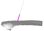
25. Ensure that the ACK ELT Whip Antenna is straight pointed AFT after installation.
Figure 240. ACK ELT Top View
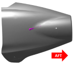
Figure 241. ACK ELT Forward Looking Aft
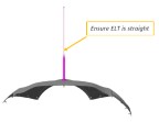
Figure 242. ACK ELT Side View
26. Using isopropyl alcohol, thoroughly and carefully clean the top of the ACK ELT Whip Antenna. (Figure 234)
Verification Method
Perform ELT unit self-test according to SELF TESTS of Section 9 of ACK Technologies Inc. Model E-04 ELT Installation/Operation Manual, or ELT Battery
Self Test
For Aera 796 aircraft, perform a transponder functional test for transmission on 121.5 MHz and 406 MHz. If the control unit was replaced, configure the transponder. See 00560-00-AQ--TRiG TT21/TT22 Mode S Transponder Installation Manual.
For G3X aircraft, perform a transponder functional test for transmission on 121.5 MHz and 406 MHz. If the control unit was replaced, configure the transponder. See 190-01499-10 Garmin GTX 34R/45R Installation Manual and 190-01115-01 Garmin G3X/G3X Touch Installation Manual.
Parent topic