Inspect Wing Pins
100311-00
Check for excess play in the wing pins.
Applicable Aircraft Serial Numbers
All
Type of Maintenance
Line
Level of Certification
LSA-RM
Task Specific Training Required
Training in the use of precision measuring instruments such as Outside Micrometer and Precision Pin Gauges
Special Tools Required
Outside Micrometer for outside diameters
Precision Pin Gauges for inside diameters
Parts Required
ICA007614 (WING LOCKING PIN, FWD), if replacement needed
ICA007615 (WING LOCKING PIN, AFT), if replacement needed
Aircraft System and Number
15—Wing Fold Mechanism
Safety Equipment
As Needed
Consumables
MOLYKOTE™ G-4700
Figure 468. Wing pins location.
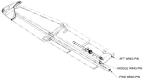
Figure 469. Wing pin dimensional checks.
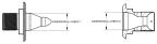
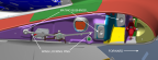
Figure 470. Wing pin mating bushings and wing locking pins.
Note:
The wings must be folded in order to perform this inspection. For the aft mating bushing, inspection can be completed by unlocking the wing lock and pulling the wing out of the bushing for access. Ensure the wings are supported to prevent accidental contact with the ground.
Task Instructions
1. Using a rag, clean the six wing pins, six bushings, and four locking pins to remove any foreign material in the joint. Each wing pin has a mating bushing on the inboard side of the wing joint.
Note:
The wing pins and bushings are not easily replaceable. Metal shavings in the grease is a symptom of wear that should be monitored closely for prevention of significant maintenance.
2. Measure the wing pin diameter and bushing bores on both the left and right wings and compare to the target values in the table below.
Name/Part | Dimensional Check 1 [in] | Dimensional Check 2 [in] |
|---|---|---|
Forward Wing Pin | Ø 0.9908 | Ø 1.0153 |
Middle Wing Pin | Ø 0.9952 | Ø 1.0129 |
Aft Wing Pin | Ø 0.4702 | Ø 0.5431 |
3. Visually inspect all wing pins and bushings for wear or damage.
4. Measure the locking pin diameters on both the left and right wings and compare to the target values in the table below.
Name/Part | Dimensional Check 1 [in] | Dimensional Check 2 [in] |
|---|---|---|
Forward Wing Locking Pin | Ø 0.3035 | NA |
Aft Wing Locking Pin | Ø 0.2400 | NA |
5. Apply a thin coat of MOLYKOTE™ G-4700 to the wing pins, bushings, and locking pins.
Verification Method
If the wing pin dimensions are above the target values and the bushing dimensions are below the target values, then the wing pin fit is acceptable. If not, then contact ICON Aircraft for further information.
Any cracks found in the wing pins or bushings should be investigated further. Do not fly the airplane and contact ICON for further instructions.
If the wing locking pin dimension is above the target values, then the locking pin fit is acceptable. If not, replace all wing locking pins below the target values. (Wing Lock Handle Removal Step 4.)
Parent topic