Install Canopy Latch Mechanism
100741-00
Use the following procedure to install the canopy latch mechanism.
Applicable Aircraft Serial Numbers
00130+
Type of Maintenance
Line
Level of Certification
LSA-RM
Task Specific Training Required
No
Special Tools Required
None
Parts Required
ME001165 (CANOPY LATCH HANDLE, SUBASSY)
ICA014035 (CANOPY LATCH PLATE)
2x MS21043-3 (NUT)
2x NAS1149C0363R (WASHER, FLAT, CRES, .188 X .063, PSVT)
2x ICA014032 (FLANGE BUSHINGS)
MS16624-4075 (RETAINING RING)
ICA014544 (WAVE SPRING)
ICA014160 INTERIOR LATCH HANDLE
ICA014545 (SET SCREW)
ICA014038 (LATCH ARM)
ICA014039 (LATCH ROLLER)
Aircraft System and Number
02—Doors and Windows
Safety Equipment
As Needed
Consumables
ICA012078 (LUBRICANT, GENERAL PURPOSE)
EA9394 (HYSOL ADHESIVE)
TT-I-735A or equivalent (ISOPROPYL ALCOHOL)
Task Instructions
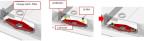
1. Install latch assembly guide plate onto click bond studs inside canopy frame.
2. Using isopropyl alcohol, clean surfaces where lubricant will be applied. Apply lubricant liberally to threads and shank of studs.
Note:
Click bond studs should already be installed.
3. Temp install washer and nut onto the short stud on the opposite side. Nuts will be torqued at later step.
Figure 23. Latch Assembly Guide Plate
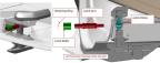
4. Prep surfaces for bonding by abrading and cleaning area with isopropyl alcohol. Using alignment tool, install two bushings into the canopy frame using Hysol adhesive. Clean off any excess adhesive squeeze out. Allow Hysol adhesive to cure before continuing with the latch install. A heating lamp can be used to accelerate the cure time of the Hysol adhesive. Apply 150° F for 1 hour to accelerate cure speed.
Figure 24. Prep Surfaces
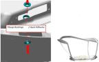
CAUTION:
Check the temperature of the carbon parts that the heating lamp is warming. Do not let the temperature get over 200° F. If the temperature gets too close to 200° F, move the heating lamp farther away from the work area.
5. After the Hysol adhesive is cured, verify that there is no excess adhesive inside the bearing surfaces. Remove excess adhesive if necessary.
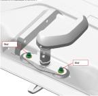
6. Install exterior canopy latch handle and wave spring into canopy frame. Insert the latch handle going from the exterior face to the interior face. Secure in place with retaining ring. Align the shaft flats during install into the canopy bushings and lock plate.
Figure 25. Canopy Latch Handle
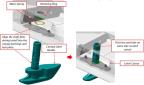
Note:
Ensure that the latch is oriented as shown. The flat face on the shaft is facing the same side as the latch cutout.
7. Install interior handle onto canopy latch assembly. Secure interior handle to shaft using set screw.
Figure 26. Interior Latch Handle
8. Use key to unlock latch assembly. With the latch assembly unlocked, rotate the handle and verify that handle does not bind up in any spots.
9. Torque nuts to 25-28 in-lbs.
Figure 27. Torque Nuts
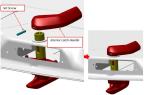
10. Install latch arm and roller assembly into canopy latch shaft through the slot as shown. Attach to the latch piston inside of the canopy latch handle assembly.
Note:
Make sure to install arm assembly in proper orientation, with the arm extending out through the latch cutout.
Figure 28. Latch Arm Orientation
Verification Method
Perform canopy latch rig/lateral position rig. (Canopy
Latch Rig)
Parent topic