Install Engine Indication System (EIS)
100334-01
Use the following procedure to install the Engine Indication System (EIS).
Applicable Aircraft Serial Numbers
00139+
Type of Maintenance
Line
Level of Certification
LSA-RM
Task Specific Training Required
No
Special Tools Required
None
Parts Required
ICA014689 (ENGINE INDICATION SYSTEM, GEA 24, GARMIN)
(4) 10F37MTT3 (SCREW, MACH TRH, 6LOBE, 10-32X.375, CRES)
Aircraft System and Number
10—Instruments (and Avionics)
Safety Equipment
As Needed
Consumables
None
Figure 244. EIS Installed-View Looking AFT at LHS Crossbeam
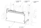
Task Instructions
2. Secure EIS with #10 screws. Torque to 25-28 in-lbs.
3. Secure connectors D9144P and D9145P from the Fuselage Wire Harness to the EIS.
6. Re-install hood shell. Slide it forward into the clip hole and then press it down on the instrument cluster.
Verification Method
Complete the Engine Test Run. (Engine
Test Run)
Parent topic