Install Exhaust System (00110+)
100336-01
Use the following procedure to install components of the Exhaust System.
Applicable Aircraft Serial Numbers
00110+
Type of Maintenance
Line
Type of Certification
LSA-RM
Task Specific Training Required
No
Special Tools Required
None
Parts Required
842950 (LOCK NUT M8-WS12)
Aircraft System and Number
13—Propulsion
Safety Equipment
As Needed
Consumables
ICA012067 (LUBRICANT, ANTI-SEIZE, NICKEL GRADE)
Task Instructions
1. Install FWD header on cylinder, being careful not to damage cylinder stud threads.
2. Install new M8 lock nuts and tighten until snug. Do not torque yet.
3. Apply a thin coat of anti-seize to FWD header slip joint interface.
4. Install Muffler/Inner Muffler Shield assembly onto FWD header and install T-15 Torx countersunk screw at FWD corner of Inner Muffler Shield.
5. Apply a thin coat of anti-seize to AFT header slip joint interface.
6. Install AFT header on cylinder, being careful not to damage cylinder stud threads.
7. Install new M8 lock nuts and tighten until snug. Do not torque yet.
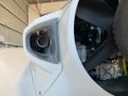
8. Temporarily install Outer Muffler fairing and verify tailpipe is centered in exhaust bezel. Adjust headers/muffler assembly as necessary. The tailpipe should align with the counter bezel.(Figure 390 While outer muffler fairing is temporarily installed, verify there is ample space between muffler and fairing to avoid burning fairing substrate.)
Figure 390. Exhaust System
9. Torque FWD and AFT header lock nuts to 133 in-lbs.
10. If EGT sensors were removed, apply anti-seize to EGT header boss and install EGT sensors. Torque to 228 in-lbs.
Verification Method
Perform Engine Test Run paying particular attention to exhaust leaks. (Engine
Test Run)
Parent topic