Install Magnetometer
100356-01
Use the following procedure to install and configure the magnetometer.
Applicable Aircraft Serial Numbers
00139+
Type of Maintenance
Line
Level of Certification
LSA-RM
Task Specific Training Required
No
Special Tools Required
None
Parts Required
ICA014694 (MAGNETOMETER, GMU 11, GARMIN)
ICA014688 (CAN TERMINATION ADAPTER)
ICA015474 (MAGNETOMETER BRACKET)
4x NAS1149CN632R (WASHER, FLAT, CRES, 36X.032, PSVT)
2x NAS1149CN432R (WASHER)
3x NAS1149CN832R (WASHER)
4X 6C50MTT3 (SCREW)
4x MS21043-06 (NUT, SLFLKG, RDC HEX, CRES, 6-32)
3x MS21043-08 (NUT)
Aircraft System and Number
10—Instruments (and Avionics)
Safety Equipment
As Needed
Consumables
ICA012078 (LUBRICANT, GENERAL PURPOSE)
TT-I-735A or equivalent (ISOPROPYL ALCOHOL)
Task Instructions
1. Apply lubricant liberally to threads and shank of the screws.
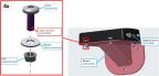
2. Mount the magnetometer to the mount bracket using 4x screws (6C50MTT3), 4x washers (NAS1149CN632R), and 4x nuts (MS21043-06).
3. Torque nuts to 8.0-9.5 in-lbs. Ensure at least one full thread is protruding from the nut.
Figure 245. Mount the Magnetometer to the Mount Bracket
4. Locate D9142P connector in wing and route out of access hole. Attach the CAN termination adapter and D9142P to the magnetometer using 2x washers (NAS1149CN432R) and screws from D9142P as shown in Figure 246 to ensure proper thread engagement of the screwlocks.
Figure 246. Attach the CAN Termination Adapter
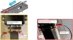
Note:
If the D9142P screws do not engage properly, remove one washer and replace with ring terminal as shown in Figure 246.
5. Using isopropyl alcohol, clean surfaces where lubricant will be applied.
6. Apply lubricant liberally to threads of the studs.
7. Mount the magnetometer-mounting bracket assembly with harness facing outboard, onto the three studs located on the wing spar. Secure using 3x nuts (MS21043-08) with 3x washers (NAS1149CN832R).
Figure 247. Mount the Magnetometer-Mounting Bracket
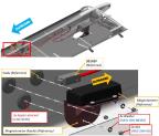
8. Torque the nuts to 11.3-13.3 in-lbs. Ensure at least one threat protruding from the nut.
10. Complete the following procedures from section MAG (Magnetometer) Configuration, per latest G3X Installation Manual (190-11115-01):
a. Unit Orientation (should be configured to Connector Port), section 35.4.8.1
b. Magnetic Interference Test, section 35.4.8.2
c. Magnetometer Calibration, section 35.4.8.3
Verification Method
Successful completion of the final step.
Parent topic