Nose Landing Gear (NLG) Actuator Rigging and Actuator Stop Switches Inspection
100704-00
The following procedure should be used to inspect the Nose Landing Gear (NLG) actuator rigging and actuator stop switches.
Applicable Aircraft Serial Numbers
00012 and 00021+
Type of Maintenance
Line
Level of Certification
LSA-RM
Task Specific Training Required
No
Special Tools Required
NLG Rigging Pin 0.1885-0.1875 in. diameter
NLG go-no-go checking pin 0.163-0.164 in. diameter)
Electrical Multimeter with resistance function
Parts Required
ICA013161 (NOSE LANDING GEAR ACTUATOR)
Aircraft System and Number
11—Landing Gear
Safety Equipment
As Needed
Consumables
TY24MX (CABLE TIE, NYLON 6-6, 30LB, 5.50)
Task Instructions
1. Remove the main landing gear, 15A, fuse from the overhead console. Safe this fuse. It will be reinserted after the test is complete.
3. Fold the wings of the aircraft. This will move the center of gravity aft so that it is easier to lift the nose up and down during the NLG rigging checks.
5. Have a foam block or equivalent nearby that can be placed under the aircraft on the keel aft of the NLG wheel well that will allow the nose wheel of the aircraft to have approximately 1 in or more clearance from the ground. This block will need to be removed numerous times during the procedure to place weight on the NLG.
Check the resistance of the NLG stop switches
6. Ensure the landing gear switch is down.
7. Turn on master power and ensure that the landing gear position indicator indicates that the landing gear is down.
8. Turn master power off.
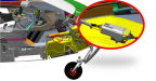
9. Disconnect the NLG actuator 8 pin connector. ()
Figure 337. NLG Electrical Connector
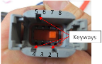
10. Confirm the NLG actuator side of the connector pins are labeled.
11. Using a multimeter set to resistance, measure resistance between the following pins and record the value. (Figure 338)
Note:
It is important that the meter not be set to just an audible continuity setting—a resistance reading in Ohm, Kilo Ohm, or Mega Ohm range is required.
Between Pins | Value if NLG is Down | Measured Value |
|---|---|---|
2 & 7 | Overload / Open | |
3 & 4 | <1 Ohm | |
2 & 4 | Overload / Open | |
5 & 6 | Overload / Open | |
6 & 7 | <1 Ohm | |
5 & 7 | Overload / Open |
Figure 338. Pins
Note:
The resistance value should be either Overload / Open or less than 1 Ohm. If the value is above 1 Ohm during the resistance checks then stop. The stop switch is bad and the actuator needs to be removed from service.
12. After completing the stop switch resistance checks, reconnect the NLG actuator connector and resecure the connector to the ty-block using a TY24MX ty-rap. The landing gear should be swung to confirm satisfactory actuation after reconnecting this connector.
Nose Landing Gear Rigging Check
13. With normal resting aircraft weight on the NLG check:
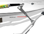
a. If a .163 in. rigging pin can be inserted into the NLG rigging hole, move to Step 14. (Figure 339)
b. If not, the nose landing gear needs to be re-rigged using a 0.1885-0.1875 rigging pin. (Nose Landing Gear (NLG) Rigging and Check
with Landing Gear Down (00021+))
Figure 339. Location of the NLG Rig Pin Hole
14. Lift the aircraft nose enough to slide a block under the keel to allow the nose wheel to be approximately 1” or greater off the ground.
15. Ensure the 15 amp main landing gear fuse is removed.
16. Turn the Master Switch on.
17. Move the landing gear handle to the up position and allow the NLG to move to the full up position and stop.
Note:
The landing gear position indication will still show in transit during this test since the main landing gear is still down. This is normal for this inspection.
18. Move the landing gear handle down and allow the NLG to come tfull down and stop.
19. Lift the aircraft nose enough to remove the block from under the keel and allow weight back on to the nose wheel. Push down on the nose to preload the landing gear, then release.
Note:
It is important to preload the nose briefly by pushing down with approximately 25 lb of weight (push down with hands) enough to visibly flex the nose landing gear leg.
20. Check the NLG rigging using the .163 in rig pin.
a. If a .163 in rig pin can be installed into the NLG rigging hole, repeat Steps 14-20 an additional 24 times for a total of 25 times.
b. If not, and nose landing gear has not been re-rigged, rig the NLG actuator using a .1885-.1875 rigging pin. (Nose Landing Gear (NLG) Rigging and Check
with Landing Gear Down (00021+)) Repeat Steps 14-20 an additional 24 times.
c. If at any time the NLG has been re-rigged once during this process and a .163 in rig pin is unable to be inserted during the 25 NLG cycles, the actuator stop switch is not functioning correctly and needs to be replaced.
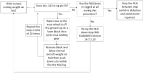
Figure 340. Summarized flow chart of the NLG rigging test procedure using a rig pin
Verification Method
See Step 20.
Parent topic