Install Oil Cooler and Thermostat (00001-00020)
100438-01
Use the following procedure is to install the Oil Cooler and Thermostat.
Applicable Aircraft Serial Numbers
00001-00020
Type of Maintenance
Line
Level of Certification
LSA-RM
Task Specific Training Required
No
Special Tools Required
None
Parts Required
9752K118 (O-RING, VITION,.644 ID x .087 W #908)
Aircraft System and Number
13—Propulsion
Safety Equipment
As Needed
Consumables
OLUBE 884-2 (LUBRICANT, O-RING PARKER O’LUBE)
LOCTITE® 243™ (THREADLOCKER, PRIMERLESS, OIL TOL, REMOVABLE MED STR, BLUE)
Task Instructions
Figure 409. Restrictor Plate Installation
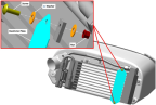
2. Lubricate two O-RINGs with LUBRICANT.
3. Install one O-RING on each of the two AN815-8D union fittings and thread a fitting into the Oil Cooler inlet and outlet so that the o-rings seal against the cooler. Torque each to 468-514 in-lbs.
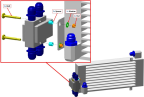
4. If the Thermostat does not have the four AN816-8D fittings installed, install them by applying THREADLOCKER to the first two threads, then torquing to finger tight then 1.5-2.5 turns additional.
5. Install the Thermostat onto the Oil Cooler as shown. Use 3/8 and 1/4 wrenches to torque the two fasteners to 20 in-lbs.
Figure 410. Thermostat Installation
6. Install the two aluminum oil lines between Oil Cooler and Thermostat using a 1 inch wrench to hold the union on the Oil Cooler, a 13/16 to hold the union on the Thermostat and a 7/8 wrench to turn the B-nuts. Torque the B-nuts to 200±50 in-lbs.
7. Install the P-clamp that attaches the Oil Cooler Outlet Line to the Oil Cooler using the #10-32 screw, nut and washer and torquing to 20 in-lbs.
8. Ensure the Bulb Seal on the Plenum Box is in good condition, then attach the Oil Cooler assembly to the Plenum Box with four MS21043-3 nuts and NAS1149C033 2R washers. Torque each nut to 20 in-lbs.
9. Connect the two hoses at the lower-AFT side of the Oil Thermostat, using a 13/16 wrench to hold the Union Fitting in the Thermostat and a 7/8 wrench to turn the B-nut. The lower hose runs aft to the Oil Pump and should be installed first. The upper hose connects to the top of the Oil Tank and should be installed second. Torque the B-nuts to 200±50 in-lbs.
10. Purge the oil system per the procedure in the Rotax 912iS Installation Manual.
11. Run the engine and check for good oil pressure and no leaks. Replenish the oil level as required.
Verification Method
The procedure is complete when the oil cooler and thermostat have been installed and the engine check shows good oil pressure and no leaks.
Parent topic