Adjust Propeller Pitch
100474-00
Use the procedure to adjust the Propeller Pitch.
Applicable Aircraft Serial Numbers
All
Type of Maintenance
Line
Level of Certification
LSA-RM
Task Specific Training Required
Yes
Special Tools Required
Digital Protractor
ITL002081 Pitch Adjustment Tool
Parts Required
None
Aircraft System and Number
13 —Propulsion
Safety Equipment
As Needed
Consumables
TT-I-735A (ISOPROPYL ALCOHOL, OR EQUIVALENT)
Masking Tape
Rubber Bands
Powder-Free Gloves
Torque Stripe
Note:
Make sure to measure from center of hub to center of the propeller blade.
Task Instructions
1. On all three blades, use tape measure to measure 25.5 inches outward from center of the hub. Place a piece of masking tape on the blade with the outer edge of the tape at 25.5 inches to mark the location. Figure 430
Figure 430. Position Pitch Adjustment Tool on Blade
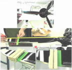
2. On one blade, place Pitch Adjustment Tool on blade with inner face aligned to the 25.5 inch mark. Secure tool to blade using rubber bands. Figure 430
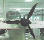
3. Rotate one blade on the left side looking forward and make sure it is level with the ground and to the trailing edge of the wing. Figure 431
Figure 431. Blade Orientation to the Ground
Note:
Perform the following steps as required until all 3 blade pitch angles are 19.2°-19.6° with attachment bolts tight. For optimal balance, all 3 pitch angles should differ from one another by no more than 0.1°.
Figure 432. Calibrate Digital Protractor
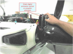
Note:
Do not bump the aircraft after calibration.
5. Carefully move the digital protractor and put the digital protractor on the pitch adjustment tool in the same vertical orientation and measure angle of blade. Figure 433
Figure 433. Measure Angle of Blade
6. Continue to verify pitch angle of all blades through Step 4 and Step 5 and record the angles.
7. If the blade angle is not within the optimal pitch angles or differ from one another by more than 0.1° then proceed to Step 8 for adjustment.
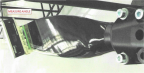
8. Using a fine tip silver marker, draw small witness mark across the blade/hub interface as shown and loosen the bolt. Figure 434
Figure 434. Adjust Angle of Blade
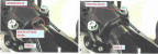
9. Rotate blade to adjust pitch angle to 19.4°.
10. Tighten the bolts incrementally to ensure the blade in hub is secure.
11. Move tool to the next blade and repeat Step 8 for the next blade.
12. Verify pitch angle of all blades throughout process.
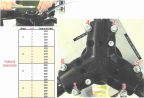
13. Torque 6x fasteners according to the sequence. Measure pitch angle of each blade periodically throughout the sequence to ensure it stays between 19.2°-19.6°. Figure 435
Figure 435. Torque and Sequence
14. Apply torque stripe to 6x bolts.
Verification Method
Verify propeller tracking is within 3/16 inch.
Parent topic