Propeller Assembly
100475-01
Instructions for assembling the Sensenich propeller prior to installation onto the Rotax engine.
Applicable Aircraft Serial Numbers
All
Type of Maintenance
Line
Level of Certification
LSA-RM
Task Specific Training Required
No
Special Tools Required
Calibrated Torque Wrench
Parts Required
ICA015027 (PROPELLER, 3 BLADE, SQUARE TIP)
Aircraft System and Number
13—Propulsion
Safety Equipment
As Needed
Consumables
None
Task Instructions
1. Obtain hardware from propeller kit. Discard hardware not listed.
a. 1X 3B SERIES HUB MOUNT HALF
b. 1X 3B SERIES HUB COVER HALF
c. 3X COMPOSITE PROPELLER BLADE
d. 6X M8 X 1.25 X 40MM CLAMPING HARDWARE (BOLT)
e. 6X NL8 SP NORD-LOCK WASHER
2. Record serial numbers of propeller blades and hubs in logbook.
3. Place the roots of the propeller blades into the pockets on the hub mount half according to the pattern provided by the included Sensenich paperwork. Orient the blades (pitch pins on top). (Figure 436)
Figure 436. Assemble Propeller Blades into Hub
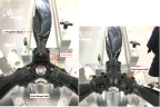
4. Place the hub cover half over the hub mount half and the blade roots.
5. Install and hand-tighten clamping hardware. The blades should still be able to rotate in the hub.
Note:
Do not torque fasteners at this time.
6. Propeller is ready to be installed on aircraft. Pitch adjustment/torquing will be done once installed.
Verification Method
Visually verify that the blade roots are installed in the hub with the hub cover secured by hand-tight clamping hardware.
Parent topic