Remove Fuse Box and Regulators
100509-00
Use the following procedure to remove the fuse box and the two regulators.
Applicable Aircraft Serial Numbers
All
Type of Maintenance
Line
Level of Certification
LSA-RM
Task Specific Training Required
No
Special Tools Required
None
Parts Required
None
Aircraft System and Number
13—Propulsion
Safety Equipment
As Needed
Consumables
None
Task Instructions
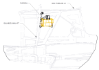
1. Remove the AFT bulkhead baggage panel. (Removal
and Installation of Inspection Panels and Fairings)
Figure 416. Left View of Fuselage, Fuse Box, and AFT Bulkhead
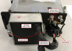
◦ Connector D9069P from fuselage wire harness
◦ Connector D9106P from engine LANE B extension wire harness
◦ Connector D9104P from engine LANE A extension wire harness
Figure 417. Fuse Box and Connectors
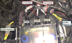
Figure 418. Regulator B Side Ground Terminals (Left). Regulator A Side Ground Terminals (Right).
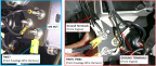
4. Disconnect Regulator A (black) and Regulator B (gray) connectors.
5. Remove the ring terminals from the ground studs on both sides of the fuse box.
◦ Terminals T9077, T9079, and T9081 from fuselage wire harness
◦ All ring terminals from ROTAX wire harness
6. Remove four 8-32 x 0.375 screws and washers to remove fuse box. Retain hardware for re-installation.
7. Remove the ground terminals from the ground studs. Retain hardware for re-installation. Fuse box components are labeled by number. Figure 419
◦ For Regulator A, Remove one M4 lock nut (16) and washer (17) to remove two black ground wires (7) on one ground stud. Figure 420
◦ For Regulator B, remove two black ground wires (7). Figure 421
Figure 419. Fuse Box Exploded View
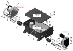
Figure 420. Regulator A Side of Fuse Box
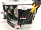
Figure 421. Regulator B Side of Fuse Box
8. Remove two M6 lock nuts (12) and washers (13) to remove the regulator from the fuse box.
9. Remove nine M4x16 Allen screws (10) and plastic washers (11) to remove the fuse box cover.
10. Loosen the strain relief (8,9).
11. Remove the ring terminals inside the fuse box. Remove a M5 lock nut (15), M4 lock nuts (16), and washers (14,17).
12. Feed the regulator wiring out of the strain relief.
13. If required, repeat Steps 7-12 to remove the second regulator.
Verification Method
The task is completed when the fuse box and regulators have been removed.
Parent topic