Replace Overhead Console Fuses
100534-01
Use this procedure to replace any indicated fuse mounted in the overhead console shown in Figure 218.
Applicable Aircraft Serial Numbers
All
Type of Maintenance
Line
Level of Certification
Owner/Pilot
Task Specific Training Required
No
Special Tools Required
None
Parts Required
ICA011204 (FUSE, 5A, EAASYID)
ICA011205 (FUSE, 7.5A, EASYID)
ICA011328 (FUSE, 15A, EASYID)
ICA011203 (FUSE, 20A, EASYID)
Aircraft System and Number
10—Instruments (and Avionics)
Safety Equipment
As Needed
Consumables
None
Figure 218. Bottom view of overhead console and fuses.
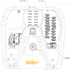
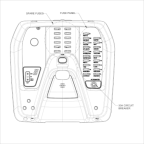
Figure 219. Overhead Console, Autopilot Configuration
Task Instructions
1. Use and the associated table to identify the blown fuse to replace.
Note:
A blown fuse will light up when the master switch is ON. Alternatively, visually check that the fuse is blown by removing it from the fuse panel.
2. Pull down on the fuse to remove it from the overhead fuse panel.
3. Select the appropriate spare fuse. The spare fuses are located in the middle of the overhead console as shown in Figure 218. The fuse should match the blown fuse in both color and amp rating. Discard the blown fuse.
4. Insert the spare fuse firmly into the appropriate location identified in Step 1.
Figure 220. Fuse Panel
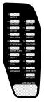
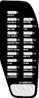
Figure 221. Fuse Panel, Autopilot Configuration
Fuse ID | Description | Sub Components | Reference |
|---|---|---|---|
INSTR 3 | Secondary Power | Annunciator panel | |
DAC | |||
Engine relays | |||
ENG BKUP | Engine Backup Power | Engine | |
12V/USB | Outlets | 12V outlet | |
USB outlet | |||
INT LIGHTS | Interior Lights | Lighting controller | |
Dome light | |||
STROBE/NAV | Anti—Collision Lights—Position | RH ACL-position | |
LH-ACL-position | |||
Strobe controller | |||
WATER RUDR | Water Rudder | Actuator | |
INSTR 1 | Instruments | Gauges | |
Backlight potentiometer | |||
Hour meter | |||
Transponder | |||
TRIM | Pitch Trim | Actuator | |
MAIN GEAR | Main Landing Gear | Actuator | |
MASTER | Master Contactor | Contactor | |
HEAT | Cabin Heat | Fan | |
Solenoid valve | |||
ANNUNC | Annunciators | Annunciator panel | |
Trim annunciator | |||
Fuel level sensor | |||
Fuel low sensor | |||
Bilge sensor | |||
Water rudder LED | |||
Bilge pump LED | |||
TAXI/LAND | Taxi-Landing | LH taxi-landing | |
RH taxi-landing | |||
BILGE | Bilge Pump | Bilge Pump | |
INSTR 2 | Instruments | GPS | |
VHF radio | |||
DAC | |||
MSC | |||
FLAPS | Flaps | Actuator | |
NOSE GEAR | Nose Landing Gear | Actuator | |
ENG/GEAR | Relays | LANE A relay | |
LANE B relay | |||
Fuel pump 1 relay | |||
Fuel pump 2 relay | |||
Starter relay | |||
Main gear up relay | |||
Main gear down relay | |||
Nose gear up relay | |||
AUTOPILOT | Autopilot | Autopilot | |
Roll Servo | |||
Pitch Servo |
Verification Method
1. Turn the master switch on. Verify that the fuse does NOT light up.
2. Check the correct function of the system associated with the replaced fuse.
Parent topic