Wing Lock Catch Adjustment
100635-00
Operate the wing lock handle and verify correct function. The initial handle pull out force from the stowed and locked position should be about 7 lbf. If not, then the wing lock catch may need to be adjusted using the procedure below.
Applicable Aircraft Serial Numbers
All
Type of Maintenance
Line
Level of Certification
LSA-RM
Task Specific Training Required
No
Special Tools Required
None
Parts Required
None
Aircraft System and Number
14—Wing
Safety Equipment
As Needed
Consumables
LOCTITE®243™
Task Instructions
1. Locate the ICA008702 wing lock catch housing. It mounts to the wing lock switch plate and contains two opposing spring-loaded balls that pinch a feature in the wing lock handle, thus creating a detent that helps hold the handle in the up and locked position (See Figure 466).
Figure 466. Wing Lock Catch
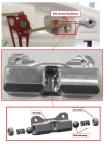
2. Use a 3/16 hex wrench to remove a set screw from one end of the housing. Use care not to lose the spring and ball that lie under the screw.
3. Apply LOCTITE® 243™ to the threads of a 91318A650 hollow-lock set screw.
4. Insert the ball, then the spring into the housing.
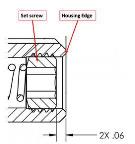
5. Install the set screw so that the spring is compressed against the ball and the head of the screw is set to a depth of .06±.01 below flush (see Figure 467).
Figure 467. Set Screw
6. Repeat the above steps for the other set screw in the housing.
Verification Method
From the up and locked position, unlatch the handle locking pawl and pull the handle down. The force needed to displace the handle from the grasp of the lock catch should be 7±2 lbf. Adjust the housing set screws equally, together in or out, to achieve this force.
Parent topic