Install Individual Center Stack Components (G3X)
100748-00
Use the following procedure to install individual center stack components on G3X equipped aircraft.
Applicable Aircraft Serial Numbers
00123+
Type of Maintenance
Line
Level of Certification
LSA-RM
Task Specific Training Required
No
Special Tools Required
None
Parts Required
r13-133a-01 (SWITCH, SPST, 30A)
ICA011040 (INDICATOR, LANDING GEAR POSITION)
2X MS16995-9 (SCREW, CAP HD, SCH-HEX, CRES, 4-40X.250)
ICA005939 (SWITCH, SPDT, LANDING GEAR)
ICA009187 (GRAPHIC OVERLAY, LANDING GEAR POSITION)
90291A103 (SET SCREW, 4-40X.125, SOFT-TIP)
ICA007743 (KNOB, SWITCH, LANDING GEAR)
50J5140-4 (WASHER, NON-TURN, K-STYLE)
ICA011228 (SWITCH, 1 POLE, ROTARY, SOLDER, 3-POSN)
ICA007742 (KNOB, SWITCH, FLAP SELECTOR)
90291a103 (SET SCREW, 4-40X.125, SOFT-TIP)
ICA015379 (POTENTIOMETER, HEATER KNOB, 320 DEG)
ICA015381 (SPACER, POTENTIOMETER, HEATER KNOB)
ICA015453 (SET SCREW, HEX, CUP-POINT, BLACK OXIDE STEEL, #4-40 X .375)
ICA015380 (KNOB, SWITCH, 320 DEG, HEATER)
ICA007533 (SWITCH, 2P SPDT)
ICA013683 (INDICATOR, TRIM POSITION)
ICA009654 (LED, ORNG, REAR PNL MNT, 3MM, RH)
ICA009655 (LED, ORNG, REAR PNL MNT, 3MM, LH
Aircraft System and Number
03—Electrical System
Safety Equipment
As Needed
Consumables
ICA012078 (LUBRICANT, GENERAL PURPOSE) Tef-Gel®
TT-I-735A or equivalent (ISOPROPYL ALCOHOL)
LOCTITE® 220™
Task Instructions
1. If applicable, install Autopilot (AP) controller unit. See steps 5-11 of Install
Autopilot (AP) Control Panel.
3. Install rocker switches to bezel. [r13-133a-01 (SWITCH, SPST, 30A)]
a. Install switch into recess of bezel.
b. Install plastic nut on back side of switch, finger tight.
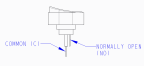
c. Install T9302 (NO) and T9304 (C) to land light.
d. Install T9303 (NO) and T9305 (C) to taxi light.
e. T9309 (NO) and T9306 (C) to bilge light.
f. T9301 (NO) and T9307 (C) to strobe light.
g. T9300 (NO) and T9308 (C) to NAV light.
h. Confirm switches actuate normally and all hardware is secure.
4. Install landing position indicator. [ICA011040 (INDICATOR, LANDING GEAR POSITION); 2X MS16995-9 (SCREW, CAP HD, SCH-HEX, CRES, 4-40X.250)]
a. Apply Tef-Gel to threads of 2X 4-40 CAP HEAD SCREWS and install landing gear position indicator onto back side of bezel with slotted openings for gear position indicator using screws. Torque to 5.7 ± .1 in-lbs. Electrical connector socket should be on top.
b. Install electrical connector D9045P into indicator board.
5. Install landing gear switch. [ICA005939 (SWITCH, SPDT, LANDING GEAR); ICA009187 (GRAPHIC OVERLAY, LANDING GEAR POSITION); 90291A103 (SET SCREW, 4-40X.125, SOFT-TIP); ICA007743 (KNOB, SWITCH, LANDING GEAR)]
a. Apply Tef-Gel to threads of landing gear switch. Insert landing gear switch into keyed hole of bezel. Install locking washer and nut over front of switch. Torque nut to 13-15 in-lbs.
b. Remove adhesive backing and install graphic overlay cover into recess on bezel.
c. Apply Tef-Gel onto thread of soft tip set screw and install landing gear knob onto landing gear switch using set screw with hole for set screw facing up. Torque set screw to 2-4 in-lbs.
d. Install electrical connector D9094J to P.
6. Install flap lever switch. [50J5140-4 (WASHER, NON-TURN, K-STYLE); ICA011228 (SWITCH, 1 POLE, ROTARY, SOLDER, 3-POSN); ICA007742 (KNOB, SWITCH, FLAP SELECTOR); 90291a103 (SET SCREW, 4-40X.125, SOFT-TIP)]
a. Remove and retain nut and locking washer from switch. Unscrew original switch knob and discard.
b. Clean flap switch and set screw threads with isopropyl alcohol and apply Tef-Gel onto threads.
c. Install K-style washer into keyed slot for flap selector on back side of bezel.
d. Install flap switch into keyed hole in bezel, install lock washer and nut to secure in place. Torque nut to 13-15 in-lbs.
e. Install flap selector knob over switch and secure in place by installing set screw. Torque to 2-4 in-lbs. Lever should be pointed in line with 0 marking on front face of instrument bezel when switch is in its most clockwise position.
f. Install electrical connector D9061J to P.
7. Install heater knob. [ICA015379 (POTENTIOMETER, HEATER KNOB, 320 DEG); ICA015381 (SPACER, POTENTIOMETER, HEATER KNOB); ICA015453 (SET SCREW, HEX, CUP-POINT, BLACK OXIDE STEEL, #4-40 X .375); ICA015380 (KNOB, SWITCH, 320 DEG, HEATER)]
a. Remove nut and lock washer from heater potentiometer.
b. Install heater knob spacer over heater potentiometer such that the key hole on the right side face of the potentiometer aligns with the cutout in the spacer.
c. Install heater potentiometer into bezel such that the keyed feature from the spacer aligns with the keyed feature in the bezel.
d. Clean threads of heater potentiometer with isopropyl alcohol and apply Loctite 220. Install lock washer and nut to secure potentiometer onto bezel. Torque nut to 7-15 in-lbs while holding the potentiometer firmly in place.
e. Install electrical connector D9084J to P.
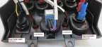
8. Install water rudder switch. [ICA007533 (SWITCH, 2P SPDT)]
a. Apply Tef-Gel to threads of water rudder switch and install into square recess of bezel with blue wire on top.
b. Install plastic nut and torque to 1-2 flats of nut past finger tight.
c. Install electrical connector D9060P to J.
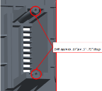
9. Install trim indicator (G3X) [ICA013683 (INDICATOR, TRIM POSITION)]
a. If necessary, drill open holes in bezel for trim position indicator to .070” diameter x .5”-.75” deep.
b. Remove and retain 2x screws from back of trim position indicator. Discard housing.
c. Insert trim position indicator into back of bezel.
d. Clean screw threads and isopropyl alcohol and apply Tef-Gel. Install 2x screws into indicator. Torque screws to 6-10 in-lbs.
e. Install electrical connector D9046J to P.
10. Install LED indicator light installation. [ICA009654 (LED, ORNG, REAR PNL MNT, 3MM, RH); ICA009655 (LED, ORNG, REAR PNL MNT, 3MM, LH)]
a. Install LED indicators into light openings on bezel.
b. For ICA009654, Water Rudder LED Indicator, install electrical connector D9054J to P.
c. For ICA09655, Bilge Pump LED Indicator, install electrical connector D9055J to P.
Verification Method
Confirm center stack and all components are secure.
Turn on master switch. Confirm all switches are operating properly and activating their associated function.
Perform a transponder correspondence test. If the control unit was replaced, configure the transponder. See 190-01499-10 Garmin GTX 34R/45R Installation Manual and 190-01115-01 Garmin G3X/G3X Touch Installation Manual.
Ensure VHF radio header screen turns on and is operable. Test radio transmission and receiving with an external radio.
Parent topic