796 Equipped Aircraft Transponder Troubleshooting
100759-00
The following procedure is used for troubleshooting the transponder on a G3X equipped aircraft.
Applicable Aircraft Serial Numbers
All
Type of Maintenance
Line
Level of Certification
LSA-RM
Task Specific Training Required
No
Special Tools Required
None
Parts Required
None
Aircraft System and Number
10—Instruments (and Avionics)
Safety Equipment
As Needed
Consumables
None
Task Instructions
1. Reference the following wiring diagram for pin out and harness wiring details:
TC20 Controller Does Not Communicate with Transponder
2. Disconnect D9068P (Transponder Controller Connector) and D9041J (Transponder Mode C Connector).
3. With MASTER OFF, check wiring continuity between TMAPA and TMAP2A, TMAPB and TMAP2B. Both connections must be solid for TC20 controller to function.
4. Reconnect D9041J.
5. With MASTER ON, between D9068P PIN 8 and PIN 9 should measure 6.5V. Between D9068P PIN 8 and Pin 1 should measure 6.5V.
No ADS-B IN/OUT/TIS Traffic Related Errors (NO ADS-B POS)
6. Remove engine cowling. (Remove
Engine Cowlings Steps 1-3.) Locate disconnected D9008J1 connector from engine cowling.
7. Locate and disconnect D9008J2 connector on transponder.
8. Perform a coax connector function test, using a multi meter with setting set to continuity, to ensure coax connector is still properly isolated.
a. Refer to .
b. Confirm there is NO continuity between outer contact and center contact.
c. Confirm there is continuity between outer contact and connector shell.
d. Confirm there is NO continuity between connector shell and center contact.
e. If any of the above conditions are not met at either connector, replace coax connector.
9. Get two long lead wires to troubleshoot the transponder coax cable. Using the long lead wires:
a. Verify audible continuous beep at center contact between transponder antenna coax connector at engine bay and transponder coax connector in aircraft nose.
b. Verify audible continuous beep at outer contact between transponder antenna coax connector at engine bay and transponder coax connector in aircraft nose.
c. Verify NO beep between outer contact and center contact at either connector ends.
11. If the function check for transponder coax cable passes, the issue could be either the antenna or the transponder unit.
ADS-B Out Intermittently
12. Check TC20 controller for software version (TT22.0 SW V2.13 or greater and Controller SW V1.14), if the software version is as indicated as shown in , remove TT22 Transponder (P/N 00745-00-01, Remove VHF Comm Transceiver and Transponder) and TC20 Control Head (P/N 00649-00, Remove Individual Center Stack Bezel Components (Aera 796)). Contact ICON. Ship transponder and control head for a software update.
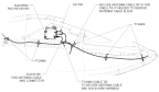
Figure 217. TN72 Receiver Mounting Location and Wire Harness Routing
14. Reseat TA50 antenna connector.
15. Disconnect D9119P (GPS receiver connector).
16. With MASTER ON, D9119P PIN 1 and PIN 2 should measure 12V.
17. Disconnect D9041J (transponder connector). With MASTER OFF, verify continuity between:
a. D9119P PIN 5 to D9041J PIN 4.
b. D9119P PIN 7 to D9041J PIN 5.
18. If power check and continuity check pass, start with slave in a known functioning TA50 antenna and perform function check. Alternatively, slave in a known functioning TN72 unit.
Verification Method
If troubleshooting fails to identify the problem, the antenna and/or transponder may need to be replaced. Contact ICON aircraft and See Remove VHF Comm Transceiver and Transponder and Install VHF Comm Transceiver and Transponder.
Parent topic