G3X Equipped Aircraft Transponder Troubleshooting
100758-00
The following procedure is used for troubleshooting the transponder on a G3X equipped aircraft.
Applicable Aircraft Serial Numbers
All
Type of Maintenance
Line
Level of Certification
LSA-RM
Task Specific Training Required
No
Special Tools Required
None
Parts Required
None
Aircraft System and Number
10—Instruments (and Avionics)
Safety Equipment
As Needed
Consumables
None
Task Instructions
1. Reference the following wiring diagrams for pin out details:
Error Message on G3X Display
2. Look for error message on G3X display, including but not limited to messages related to:
◦ ADAHRS
◦ GPS
◦ ADS-B IN
◦ ADS-B OUT
3. See 190-01115-00 Garmin Pilot’s Guide System status messages for guidance on specific messages.
Transponder and Other Aircraft Instrument Gauge Intermittent Power
4. Make sure Overhead Console INSTR 1 fuse is not blown and is seated all the way in. (See System
Wiring Diagram, Garmin G3X EIS and ADAHRS Display.)
ADAHRS and Garmin G3X Display Has Intermittent Power
6. Locate D9147P (ADAHRS connector J251) and disconnect with MASTER ON.
7. Check for 12V between PIN 7 and PIN 9.
8. Reseat D9147P connector.
9. Locate and disconnect D9146P (ADAHRS connector J252)
10. Locate and disconnect D9138J (GTX 45R Transponder Connector).
11. With MASTER OFF, check for continuity for each pin between D9138J (GTX 45R Transponder Connector) and D9146P.
12. Check for shield ground isolation at D9138J.
Transponder Information Not Showing on G3X Display
14. Locate and disconnect D9149P (G3X display connector, J4502).
15. Locate and disconnect D9138J (GTX 45R Transponder Connector).
16. With MASTER OFF, check for continuity for each pin between D9138J and D9149P.
17. Check for shield ground isolation at D9138J.
No GPS Signal and No Weather Information Displayed on G3X Display
18. Remove engine cowling. (Remove
Engine Cowlings Steps 1-3) Locate disconnected D9008J1 connector from engine cowling.
19. Locate and disconnect D9008J2 connector on the transponder.
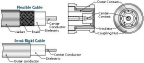
20. Perform a coax connector function test, using a multi meter with setting set to continuity, to ensure coax connector is still properly isolated.
b. Confirm there is NO continuity between outer contact and center contact.
c. Confirm there is continuity between outer contact and connector shell.
d. Confirm there is NO continuity between connector shell and center contact.
e. If any of the above conditions are not met at either connector, replace coax connector.
Figure 216. Coax Cable Layout
21. Get two long lead wires to troubleshoot the transponder coax cable. Using the long lead wires:
a. Verify audible continuous beep at center contact between transponder antenna coax connector at engine bay and transponder coax connector in aircraft nose.
b. Verify audible continuous beep at outer contact between transponder antenna coax connector at engine bay and transponder coax connector in aircraft nose.
c. Verify NO beep between outer contact and center contact at either connector ends.
23. If the function check for transponder coax cable passes, the issue could be either the antenna or the transponder unit.
Verification Method
If troubleshooting fails to identify the problem, the antenna and/or transponder may need to be replaced. Contact ICON aircraft and See and .
Parent topic