Aft Lines Replacement
100028-00
Use the following procedure to replace the aft lines.
Applicable Aircraft Serial Numbers
All
Type of Maintenance
Line
Level of Certification
LSA-RM
Task Specific Training Required
No
Special Tools Required
None
Parts Required
HDB01 Stainless Steel Braided Brake Hose
HYD-008P B-nut or HEA01 Banjo fittings as required
T25F-C0 Spiral Wrap
TY24MX Cable Tie
Aircraft System and Number
11—Landing Gear
Safety Equipment
As Needed
Consumables
F4TAPEBLACK Silicone Tape
Smooth-On Sil-Poxy
Note:
The two aft brake lines (Left and Right) that run between he brake calipers and the parking brake valve are nearly identical, differing only in their length and where they are attached and secured. Use the procedure below to replace either of them, paying attention to the differences where noted.
Task Instructions
1. Use a 7/16 wrench to hold the AN816-3D fitting on the aft port of the parking brake valve, then a 1/2 wrench to disconnect the B-nut of the aft brake line at the parking brake valve. Cap or plug the openings to minimize fluid loss.
2. Use a 14mm wrench to remove the banjo bolt and two copper washers at the MLG brake caliper.
3. Cut and remove all the cable ties holding the brake line to the structure.
4. The brake line end fitting cannot pass through the hole in the forward main bulkhead or through the guides on the aft face of the Main Landing Gear (MLG) leg, so use a pair of wire or hose cutters to cut the brake line just aft of the parking brake B-nut fitting.
5. Remove the brake line by guiding it through the bulkhead, MLG boot and MLG leg guides, pulling on the banjo end. The line is bonded with Sil-Poxy at the boot joint; work this interface being careful to not damage the boot.
6. If replacing the aft-left brake line, cut a length of hose to 114.0-inches. If replacing the aft-right brake line, cut a length of hose to 126.0-inches. Before cutting, wrap the cut location with masking tape, then cut through the tape. This will result in a neater cut of the stainless braid, making it easier to pass the hose through the MLG leg guides.
7. Terminate one end of the hose with a HYD-008P B-nut fitting. (General Brake Line Termination Procedure)
8. Starting near the appropriate brake caliper, thread the unterminated end of the brake line through the lower and upper MLG leg guides then through the clearance slot in the MLG boot and on into the MLG bay.
9. Continue routing the line under all the MLG components and through the appropriate side (LH/RH) MS35489-35 grommet in the forward main bulkhead Figure 306.
Figure 306. Forward Main Bulkhead
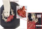
10. Connect the banjo fitting end of the brake line to the caliper, routing the line in a natural way up through the MLG leg guides. Do not put a twist in the line. Use a HYD-003P Banjo bolt and two HYD-005B copper washers as shown in Figure 307. Torque the Banjo bolt to 140 in-lbf and then torque an additional 90° of rotation.
Figure 307. Main Landing Gear
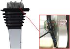
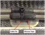
11. Cut a 3-inch length of silicon tape and wrap it around the brake line at the location of the MLG trunnion cable tie mount. Use a TY24MX cable tie to secure the line to this mount. See Figure 308.
Figure 308. Main Landing Gear Trunnion
12. Seal the slot where the brake line passes through the MLG boot by injecting Sil-Poxy into the joint and completely around the line. Leave a small fillet of Sil-Poxy all around the joint to ensure a good water seal.
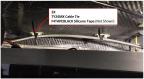
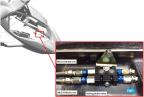
13. For the right hand brake line only: locate the two cable tie mounts on the aft bulkhead used to secure the line. Mark the location on the brake line that will secured to the mounts. Wrap a 3-inch length of silicone tape around the brake line at each mount location, then secure the line to the mounts using TY24MX cable tie at each of the two locations (see Figure 309).
Figure 309. Brake Line Replacement
14. Route the brake line to the parking brake valve. Use the above method to wrap the brake line with silicone tape and attach with a cable tire at each mounting point on the structure. Figure 310 shows a typical mount.
Figure 310. Parking Brake Valve
15. Trim excess length from the brake line if desired and terminate the parking brake valve end of the line with a HYD-008P B-nut fitting. (General Brake Line Termination Procedure)
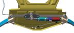
16. Connect the brake line B-nut to the parking brake valve, then use a 7/16 wrench to hold the AN816-3D fitting on the forward port of the parking brake valve, and a 1/2 wrench to torque the B-nut to 120-132 in-lbs (see Figure 311).
Figure 311. Brake Line Replacement
17. Bleed the brakes per the procedure in the Beringer manual.
Verification Method
Check for correct operation and no leaks.
Parent topic