Check Landing Gear Extended Position
100274-00
The following section contains the information required to evaluate the rigging of the landing gear components in the extended position.
Applicable Aircraft Serial Numbers
All
Type of Maintenance
Line
Level of Certification
LSA-RM
Task Specific Training Required
No
Special Tools Required
Inclinometer
Wing Jack Point Adapter—ICA009750
Parts Required
None
Aircraft System and Number
11—Landing Gear
Safety Equipment
As Needed
Consumables
None
Task Instructions
1. Remove the Aft Bulkhead Baggage Panel (Removal
and Installation of Inspection Panels and Fairings) to access the landing gear control systems.
2. Jack the aircraft using the built-in jack points. (796 Empty
Weight and CG Measurement While on Jackpoint Scales)
3. Extend the landing gear to its deployed position.
4. With the aircraft jacked and level, zero a digital protractor along the longer of the two pushrods.
Figure 298. Main Landing Gear Installation
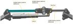
5. Move the digital protractor to the Bellcrank surface and read measurement. The measurement on the protractor should read 3.822 ± .237°. (See Main Landing Gear (MLG) Rigging and Rigging Check with
Landing Gear Down if out of tolerance.
6. Verify that the nose gear bellcrank and drag link are in line with one another in the extended position. See Nose Landing Gear (NLG) Rigging and Check
with Landing Gear Down (00001-00020) and Nose Landing Gear (NLG) Rigging and Check
with Landing Gear Down (00021+) for rig pin information and procedures.
7. Turn on master switch and verify that in the cockpit the landing gear indicator is in the landing gear down position.
8. Bring aircraft back to ground and remove jacks.
Verification Method
Parent topic