Install ADS-B GPS Antenna
100323-00
Use the following procedure to install the ADS-B GPS Antenna. Aircraft prior to ASN 00110 may not have the ADS-B Out system installed. The ADS-B Out system requires that TT22 Transponder software is V2.13 or greater and TC20 Control Head software is V1.14 or greater. This task is applicable to the Garmin 796 configuration only.
Applicable Aircraft Serial Numbers
00110+ (Varies prior to ASN 00110)
Type of Maintenance
Line
Level of Certification
LSA-RM
Task Specific Training Required
No
Special Tools Required
None
Parts Required
ICA014190 (ANTENNA, GPS, ADS-B COMPACT)
Aircraft System and Number
10—Instruments (and Avionics)
Safety Equipment
As Needed
Consumables
70006436714 (3M VHB TAPE 5915 BLACK, 1/2 IN X 72 YD 16 MIL)
TY24MX (CABLE-TIE, NYLON 6-6, 30LB 5.50, TY-RAP)
TT-I-735A or equivalent (ISOPROPYL ALCOHOL)
AC-111 (ADHESION PROMOTOR, AC-111)
ICA014234 (TAPE, PRESERVATION SEALING, 481, 3M, 1.00 BK)
Task Instructions
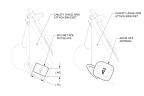
1. Mount ADS-B GPS ANTENNA to the top of the Canopy Hinge Arm Attach Bracket as shown in and as follows. Figure 272
a. Clean the surface with ISOPROPYL ALCOHOL and let it dry.
b. Apply ADHESION PROMOTOR to mating surfaces and let it dry.
c. Apply 0.75 in. of 3M VHB TAPE 5915 BLACK on the mating surface of the antenna and the bracket in the orientation shown.
d. Use about 15 psi of pressure at a temperature of 70°F.
Figure 272. Antenna Mounting
Note:
Bond cures to 75% in 1 hour, 90% in 24 hours, and 100% in 72 hours at 70°F.
2. Secure the ADS-B GPS ANTENNA to the LH Canopy Hinge Arm Tube as follows:
a. Clean the LH Canopy Hinge Arm Tube with ISOPROPYL ALCOHOL.
b. Cut 10.00±.25 in. of PRESERVATION SEALING TAPE.
c. Keeping the ADS-B GPS ANTENNA cable straight, center the tape onto the cable starting at about 3 inches from the antenna.
d. Carefully tape the cable to the LH Canopy Hinge Arm Tube along the FWD-inboard side as shown in Figure 271, Figure 273, Figure 274. The taped portion of the cable should start under the Canopy Hinge Arm Attach Bracket.
Figure 273. Antenna Routing Looking Left, Outboard. Canopy Open
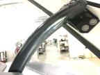
Figure 274. Antenna Routing Looking AFT. Canopy Open.
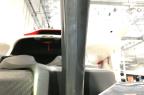
Figure 275. Antenna Routing Looking AFT-Down
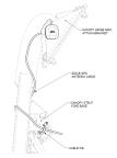
3. Continue routing the ADS-B GPS ANTENNA cable around the rectangular portion of the LH Canopy Hinge Arm Tube as shown in Figure 271.
5. Connect ADS-B GPS ANTENNA to the ADS-B GPS Receiver.
Verification Method
1. Take the aircraft outside and place in clear view of the sky.
2. Turn knob on control head to ATL mode. Wait for the display to change from ALT to GND. If not, there is something wrong with the squat switch or setting.
Note:
It may take up to 2 min for it to cycle to GND.
3. Press FN button twice on the TC20 until ADS-B POSN diagnostic screen is displayed it will display the following for position fix.
4. After 2 min the GPS should have obtained a position fix. If no fix is determined and an error of “WARNING No ADSB Pos” shows up, call ICON for further support.
Parent topic