Install Fuse Box and Regulators
100345-00
Use the following task to install the fuse box and both regulators.
Applicable Aircraft Serial Numbers
All
Type of Maintenance
Line
Level of Certification
LSA-RM
Task Specific Training Required
No
Special Tools Required
None
Parts Required
664678 (ROTAX REGULATOR A)
664679 (ROTAX REGULATOR B)
LOCTITE 222 (THREADLOCKER, ACRYLIC, REMOVABLE LOW STRENGTH)
Aircraft System and Number
13—Propulsion
Safety Equipment
As Needed
Consumables
None
Task Instructions
1. Feed the regulator wiring through the strain relief. Use part #8 for Regulator A (6) and #9 for Regulator B (5). Figure 419
3. Hand tighten the strain relief.
4. Secure the fuse box cover with nine M4x16 Allen screws (10) and plastic washers (11).
5. Secure the ground terminals to the ground studs.
◦ For Regulator A, use one M4 lock nuts (16) and washer (17) to secure two black ground wires (7) on one ground stud.
◦ For Regulator B, use two M4 lock nuts (16) and two washers (17) to temporarily secure two black ground wires (7) on separate ground studs. Additional wires will be added in subsequent steps.
6. Secure the regulator to the fuse box with two M6 lock nuts (12) and washers (13).
7. Repeat Step 1-6 if replacing more than one regulator.
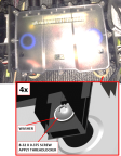
8. Secure the fuse box to the fuselage with four 8-32 x 0.375 screws and washers previously removed. Apply THREADLOCKER to screw threads. Torque to 7-9 in-lb. Figure 422
Figure 422. Close-up View of Fuse Box Mounting Screws
◦ Connector D9069P from fuselage wire harness
◦ Connector D9106P from engine LANE B extension wire harness
◦ Connector D9104P from engine LANE A extension wire harness
10. Secure the ring terminals to the ground studs with M4 nuts and washers. Do not install more than five rings on any single ground stud. Figure 418
◦ Terminals T9077, T9079, and T9081 from fuselage wire harness
◦ All ring terminals from ROTAX wire harness
11. Connect Regulator A (black) and Regulator B (gray) connectors.
12. Install the AFT bulkhead baggage panel. (Removal
and Installation of Inspection Panels and Fairings)
Verification Method
Complete the engine test run. (Engine
Test Run)
Parent topic