Install Horizontal Tail Tip Lock Switches
100347-00
Use the following procedure to install the two horizontal tail tip lock switches.
Applicable Aircraft Serial Numbers
All
Type of Maintenance
Line
Level of Certification
LSA-RM
Task Specific Training Required
No
Special Tools Required
None
Parts Required
ICA009628 Limit switch
ICA009630 Limit switch, RH
ICA009629 Limit switch
ICA009631 Limit switch, LH
Aircraft System and Number
09—Horizontal Tail
Safety Equipment
As Needed
Consumables
None
Task Instructions
1. Connect wiring harness.
a. LH switches: D9013P to D9013J, D9014P to D9014J
b. RH switches: D9015P to D9015J, D9016P to D9016J
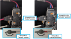
2. Install switches. (Figure 189) Torque LIMIT SWITCH screws to 8 in-lbs. Torque TAIL TIP LOCK LIMIT SWITCH screws to 2-4 in-lbs.
3. Verify the wing tip lock switch installation. Start with the wing tip lock in the “Unlocked” position. Rotate the lock handle to the “Locked” position. Verify the wing tip lock switch is engaged. The switch will click when it is fully engaged. Verify at the annunciator panel that “LOCK WING/TAIL” light is out. Figure 199
Figure 199. Verify Switch Position
Verification Method
Once the two limit switches are installed and functional, this task is complete.
Parent topic