Install Propeller Assembly Onto Engine
100362-00
Use the following instructions to install the cooling fan, extension, and propeller onto the engine flange.
Applicable Aircraft Serial Numbers
All
Type of Maintenance
Line
Level of Certification
LSA-RM
Task Specific Training Required
No
Special Tools Required
None
Parts Required
12 X 6C62MTF3-100 (SCREW, MACH FLH, 6LOBE, CRES, 6-32 X .625)
2 X ICA005858 (FAN, COOLING ENGINE, HALF, 15.5 DIA)
12 X MS21043-06 (NUT, SLFLKG, RDC HEX, CRES, 6-32)
12 X NAS1149CN632R (WASHER, FLAT, CRES, #6, .32 THK, PSVT FNSH)
2 X ICA011499 (BACKING PLATE, ENGINE COOLING FAN)
6-IN-ROTAX (EXTENSION, PROPELLER, 6.00)
6 X AN5C20A (BOLT, MACH, CRES, .312-24 X 1.563)
6 X ICA012162 (BUSHING, PROP FLANGE, ROTAX)
6 X MS20143-5 (NUT SLFLKG, RDC HEX, CRES, .312-24)
6 X NAS1149C0563R (WASHER, FLAT, CRES, .312 X .063 PSVT)
ME000832-A (PAINTED, SPINNER BULKHEAD, Serialized)
ME000636-C (PROPELLER, SUBASSY *Serialized*)
6 X MS21043-5 (NUT, SLFLKG, RDC HEX, CRES, .312-24)
6 X NAS1149C0532R (WASHER, FLAT, CRES, .312 X .032, PSVT)
6 X AN5C34A (BOLT, MACH, CRES, .312-24 X 3.06)
6 X NAS1149C0563R (WASHER, FLAT, CRES, .312 X .063, PSVT)
Aircraft System and Number
13—Propulsion
Safety Equipment
As Needed
Consumables
ICA012078 (GENERAL LUBRICANT)
Torque Stripe
Task Instructions
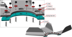
1. If required sub-assemble 2 each engine cooling fans with 6 X screws (6C62MTF3-100), 1 cooling fan half (ICA005858), 6 X nut (MS21043-06), 6 X washer (NAS1149CN632R), and 1 backing plate half (ICA11499). Ensure backing plate is oriented with beveled edge facing away from cooling fan. (Figure 437)
Figure 437. Cooling Fan Half Assembly
2. Torque 12X fasteners to 9 in-lbs.
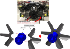
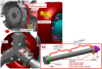
3. Install 1 propeller extension (6-IN Rotax) and cooling fan onto propeller flange using 6 X bolt (AN5C20A), 6 X bushing (ICA012162), 6 X nut (MS21043-5), 6 X washer (NAS1149C0563R). Figure 438
Figure 438. Cooling Fan to Extension Assembly
CAUTION:
Rotate engine in counterclockwise direction ONLY.
Figure 439. Fan and Extension Engine Attachment
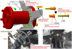
5. Ensure fan is oriented with the blades pointing away from the engine.
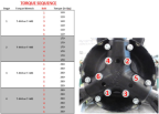
6. Torque 6 X bolts according to sequence in
CAUTION:
Rotate engine in counterclockwise direction ONLY.
Figure 440. Extension and Fan to Engine Torque Sequence
7. Ensure propeller hub is seated flush against propeller extension flange.
8. Apply torque stripe.
Figure 441. Spinner Bulkhead Attachment
10. Install propeller onto spinner bulkhead as shown using 6 X bolts (AN5C34A), 6 X washer (NAS1149C0563R), on the bolt head/propeller hub side, 6 X washer (NAS1149C0532R), 6 X nut (MS21043-5).
11. Apply lubricant to bolt shanks and under washers where they contact the propeller and propeller extension flange. Fasteners should be slightly snug. Do not torque.
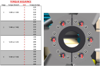
Figure 442. Propeller Torque Sequence
13. Ensure propeller hub is seated flush against propeller extension flange.
14. Don’t apply torque stripe. Torque stripe should be installed at the end of propeller balance. (Balance
Propeller)
15. Perform propeller pitch check.
Verification Method
Perform dynamic propeller balancing. (Balance
Propeller)
Parent topic