Instrument Panel Center Spine Removal and Installation
100367-00
Use the following procedure to remove and install the instrument panel center spine.This task is applicable to the Garmin 796 configuration only. For the Garmin G3X see Garmin
G3X and Autopilot Bezel Removal, Garmin
G3X and Autopilot Bezel Installation, Remove IP Center Spine, and Install IP Center Spine.
Applicable Aircraft Serial Numbers
All
Type of Maintenance
Line
Level of Certification
LSA-RM
Task Specific Training Required
No
Special Tools Required
None
Parts Required
ME000557-B PAINTED, HANDHOLD, CENTER IP
8C50MTT3 SCREW, MACH TRH, 6LOBE, CRES, 8-32X.500
Aircraft System and Number
05—Equipment and Furnishings
Safety Equipment
As Needed
Consumables
None
Task Instructions
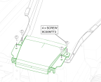
3. Remove 4x screws securing handhold from top of center console. Retain for reinstallation.
Figure 74. Remove Handhold Screws
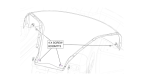
4. Remove two screws securing instrument panel center spine to the front of the fuselage. Remove two screws securing center spine to the top of the center console. Retain for reinstallation.
Figure 75. Remove Center Spine Screws
Verification Method
Task is complete when the center spine has been installed.
Parent topic