Landing Gear Actuator Limit Switch Adjustment Procedure
100391-00
There are multiple configurations of actuators in the Fleet currently. Please use applicable actuator part number and Figure 303 to identify whether this section is applicable to your aircraft actuator. If your actuator doesn’t match this part number/configuration refer to Landing Gear Actuator Limit Switch Adjustment Procedure. Use this procedure to adjust the limit switch on the desired actuator.
Applicable Actuator Part Number
ICA004001
ICA013071
ICA004000
ICA013070
Type of Maintenance
Line
Level of Certification
LSA-RM
Task Specific Training Required
No
Special Tools Required
None
Parts Required
None
Aircraft System and Number
11—Landing Gear
Safety Equipment
As Needed
Consumables
None
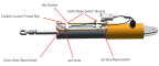
Figure 303. Landing Gear Actuator for ASN 00001-00109
Task Instructions
1. Unless already performed, remove any interior panels needed to gain access to the actuator. (Right Instrument Panel Top Panel Removal)(Removal
and Installation of Inspection Panels and Fairings)
2. Jack the aircraft so that the landing gear is clear of the ground. (796 Empty
Weight and CG Measurement While on Jackpoint Scales)
3. Use an open-end wrench to loosen the jam nut tightened against the limit switch adjustment saddle for the affected switch.
4. Loosen Set Screw from adjustment rod and rotate the adjustment rod to the desired position.
5. Torque Set Screw to 2-4 in-lbs.
6. Torque the jam nut to 36-40 in-lbs to secure the position of the limit switch.
7. Power up the aircraft, and actuate the landing gear to verify adjustment.
8. Repeat steps 3 thru 6 as needed until the landing gear is properly adjusted. (See Nose Landing Gear (NLG) Rigging and Check with Landing
Gear Up, Nose Landing Gear (NLG) Rigging and Check
with Landing Gear Down (00001-00020), Nose Landing Gear (NLG) Rigging and Check
with Landing Gear Down (00021+), Main
Landing Gear (MLG) Rigging and Rigging Check with Landing Gear Up, or Main Landing Gear (MLG) Rigging and Rigging Check with
Landing Gear Down as needed)
9. Replace the interior panels, extend the landing gear, and lower the aircraft off the jacks. (Right
Instrument Panel Top Panel Installation)(Removal
and Installation of Inspection Panels and Fairings)
Verification Method
Power up the aircraft, and actuate the landing gear to verify adjustment.
Parent topic