Main Landing Gear (MLG) Removal
100407-00
Use the following procedure to remove the main landing gear (MLG) assembly.
Applicable Aircraft Serial Numbers
All
Type of Maintenance
Line
Level of Certification
LSA-RM
Task Specific Training Required
No
Special Tools Required
ICA009749 (WING HARD JACKING POINT)
Parts Required
None
Aircraft System and Number
11—Landing Gear
Safety Equipment
As Needed
Consumables
None
The procedure below removes both left and right MLG assemblies. If only removing one side, perform only those steps needed.
CAUTION:
Whenever standing, sitting, or kneeling inside the fuselage with floor panels removed, suitable padding must be employed so as to avoid damage to the bottom of the hull. Sandwich panels and other structure and systems can be easily damaged by concentrated applied loads.
Task Instructions
2. Jack aircraft so that landing gear is clear of ground.
4. Release the parking brake.
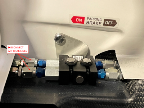
5. Use a 7/16 wrench to hold the aft union fittings at the parking brake valve, then use a 1/2 wrench to loosen the B-nuts, disconnecting the left and right brake lines from the aft side of the valve. Cap the line and valve openings to minimize brake fluid loss.
Figure 321. Disconnect Left and Right Brake Lines
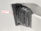
6. Use a tool such as a putty knife to separate and peel the bond between the flanges of the left and right MLG boot and the Seawings™ being careful to not damage the surfaces.
Figure 322. MLG Boot Bond Flanges
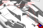
7. Remove all the cable ties that secure the left and right brake lines from the parking brake valve back to the gear.
Figure 323. Cable Ties Securing Brake Lines
8. The brake lines pass through grommets at the forward main bulkhead. Push these aft into the gear bay.
9. Supporting the weight of the left gear leg, remove the retaining ring and wrist pin securing the left MLG pushrod to the MLG bellcrank.
10. Use 15/16 wrenches to remove the two AN10C20A pivot bolts, nuts, and washers from the left
11. Withdraw the left MLG leg assembly from the aircraft, guiding the brake lines through the bulkhead.
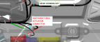
12. Disconnect the MLG actuator from the aircraft electrical harness.
Figure 324. MLG Actuator
13. Use a 3/8 wrench to remove the AN3C27A bolt washer from the top of the MLG bellcrank.
14. Supporting the weight of the right gear leg, use 15/16 wrenches to remove the two AN10C20A pivot bolts, nuts, and washers from the right MLG trunnion.
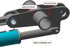
15. Remove the retaining ring from the MLG bellcrank shaft, then remove the shaft.
Figure 325. MLG Bellcrank Shaft and Retaining Ring
16. Withdraw the right MLG leg, bellcrank, and actuator assemblies from the aircraft, guiding the brake line out through the bulkhead.
17. Proceed to the Beringer Wheel and Brake Maintenance Manual if changing the tire or doing further work on the wheel.
Verification Method
The procedure is complete when the main landing gear has been removed.
Parent topic