Rigging Roll Controls
100029-00
Use the following procedure for general maintenance and for rigging the roll control system following disassembly, maintenance, and reassembly of the roll cable circuit.
Applicable Aircraft Serial Numbers
All
Type of Maintenance
Line
Level of Certification
A&P
Task Specific Training Required
No
Special Tools Required
Aircraft Cable Tensiometer
Digital Protractor
5 x DIA .1875 Rigging Pins
1 x DIA .250 Rigging Pins
Parts Required
As needed based upon inspections and condition of parts. Contact ICON Aircraft for assistance as needed. A list of part numbers in the aileron cable system is below.
Part Number | Part Name | Quantity |
|---|---|---|
ICA002294 | SOCKET ASSY, ROLL, WING FOLD | 2 |
ICA005909 | CONTROL CABLE, ROLL, FUSELAGE, UPR | 1 |
ICA008437 | CONTROL CABLE, ROLL, FUSELAGE, RH | 2 |
ICA008437 | BRACKET PLATE, PULLEY, ROLL, COCKPIT, AFT | 2 |
ICA008925 | BUSHING, FLANGE, .250X.100X.032 | 4 |
ICA008926 | BUSHING, FLANGE, .250X.132X.032 | 6 |
ICA009031 | BUSHING, PLAIN, AL, .312X.250X.620 | 2 |
ICA009850 | CABLE FAIRLEAD, OVERHEAD ROLL | 2 |
ICA012104 | CLIP, LOCKING, TURNBUCKLE, .042 WIRE | 2 |
MS20220-2 | PULLEY, GROOVE, FLIGHT CONTROL, 1680LB | 2 |
MS20392-1R23 | PIN, STR, HEADED, DRILLED SHK, CRES, .125X.719 | 4 |
MS20392-1R27 | PIN, STR, HEADED, DRILLED SHK, CRES, .125X.844 | 8 |
MS21151-7 | ROD END, BBRG, EXT THD, .250-28X.188 | 2 |
MS21251-B5S | TURNBUCKLE BODY, CLIP LKG, BRASS, .156X.250-28X2.25 | 2 |
MS21256-1 | CLIP, LKG, TRNBKL, 1.078 | 6 |
MS24566-4B | PULLEY, CONT, AFB, .188X3.01 | 4 |
MS24665-151 | PIN, COTTER, CRES, .063X.500 | 12 |
MS24694C101 | SCREW, MACH, FLAT CSK HD, .250-28X.906X.375 | 2 |
NAS77C4-007 | BUSHING, FLNGD, UNLINED, CRES, .250X.070 | 4 |
Aircraft System and Number
06—Flight Controls
Safety Equipment
As Needed
Consumables
None
Note:
Roll rigging sequence is from INBD to OUTBD
Task Instructions
1. Remove left hand and right hand forward and main cockpit floor boards. (Remove
Cockpit Floorboard)
2. Remove seat back and seat pan. (Remove Seat Back)(Seat Pan Removal) Retain all fastening hardware.
4. Remove seatbelt reel cover, left hand and right hand baggage sidewalls, and baggage headliner. (Headliner Removal) If headliner cannot be removed without removal of overhead console, temporary removal is permitted.
5. Remove aileron access panel. (Removal
and Installation of Inspection Panels and Fairings) Retain all fastening hardware.
6. Inspect all components within the roll circuit for excessive wear. Any components that show excessive wear or damage must be replaced with new components. Refer to table for component list.
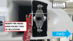
7. Install .250” diameter rig pin through the center console and forward pitch sector prior. Figure 92
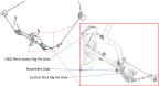
Figure 92. FWD Pitch Sector Pin Locations
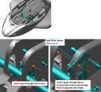
Figure 93. Rig Pin Locations—Control Stick Rig Pin Hole
9. Fold both aircraft wings and install 2X .1875 in diameter rig pins at both of the wing socket bellcrank. Figure 94
Figure 94. Rig Pin Locations
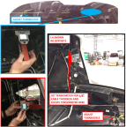
10. Use a tensiometer (upper cable thickness = 3/32 in, LH and RH fuselage cable thickness = 1/8 in) to rig the pilot side fuselage control cable, the copilot side fuselage control cable, and the upper control cable. Achieve the following, refer to Figure 95:
Note:
The bridle clamp should be removed for the Autopilot configuration.
a. Adjust turnbuckles to set cable tension on all 3 cables to 25-30 lbs.
b. After tensions are set on all 3 cables, ensure that only 3 threads or less are exposed on all cable terminal sides and only 12 threads or less are exposed on all rod end sides. Re-rig and adjust as necessary.
Figure 95. Tensiometer and Cable Adjustment Locations
11. Install turnbuckle clips into turnbuckles connecting control cables to control sticks. ICA012104 clip goes on the rod end side and the MS21256-1 clip goes on the control cable side.
12. With rig pins installed, unfold and lock both aircraft wings.
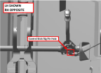
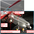
13. Install 2X .1875 in diameter rig pins through the outboard roll bellcranks. If the pin will not install, adjust length of inboard aileron push tube by adjusting rod end lengths as necessary to align the holes in the bracket and bellcrank. Adjust rod end lengths equally. Once adjusted, torque push tube jam nut to 60 in-lbs. Torque through bolt and locking nut to 20 in-lbs. Figure 96
Figure 96. Outboard Roll Bellcrank Rig Pin
15. Adjust outboard push tube rod ends equally to align aileron trailing edge with flap trailing edge within 0+/-.02 in. Once adjusted, torque push tube jam nut to 60 in-lbs. Torque through bolt and locking nut to 20 in-lbs.
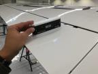
16. Secure a digital protractor to the top surface of the aileron using double sided tape or equivalent. Set the protractor to zero. Figure 97
Figure 97. Aileron Digital Protractor
17. Remove all rig pins that have been installed.
a. 2X Wing socket bellcrank rig pins
b. 2X Outboard roll bellcrank rig pins
c. Control stick rig pin
18. Ensure ailerons maximum travel limits are set as specified.
a. Trailing Edge Down: 15°+/-2°
b. Trailing Edge Up: 25°+/-2°
20. Remove FWD pitch sector rig pin.
Figure 98. Location of Secondary Roll Stop
21. Install seatbelt reel cover, left hand and right hand baggage sidewalls, and baggage headliner. If the overhead console was removed, re-install.
22. Install baggage floor boards using hardware retained during removal. (Baggage Floor Installation)
23. Install seat back and seat pan using hardware retained during removal.(Install
Seat Back)(Seat Pan Installation)
25. Install aileron access panel using retained fastening hardware.
Verification Method
Conduct the Inspect Roll Rigging procedure (Inspect Roll Rigging) to verify proper rigging.
Parent topic