Install Engine
100148-00
Use the following procedure to install the into the aircraft.
Applicable Aircraft Serial Numbers
All
Type of Maintenance
Heavy
Level of Certification
LSA-RM
Task Specific Training Required
No
Special Tools Required
3/8” Anchor Shackle (x2)
Parts Required
None
Aircraft System and Number
13—Propulsion
Safety Equipment
As Needed
Consumables
ICA012078 (LUBRICANT, GENERAL PURPOSE) Tef-Gel®
DEX-COOL 50-50 (COOLANT, ENGINE)
Task Instructions
1. Verify the orientation on the oil return line fitting at the engine prior to installation. (Figure 355) The fitting should be roughly parallel with the engine oil pan.
Note:
The orientation will be checked again with the engine installed.
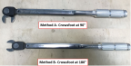
2. Verify the torque value on the oil return line fitting. Torque oil return line fitting to 300-350 in-lb if using Method A or 290-330 in-lb if using Method B. (Figure 356)
Figure 355. Oil Return Line Fitting Location
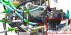
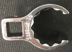
Figure 356. Method A vs. Method B (Top) 7/8” 12-Point Crows Foot Wrench (Bottom)
3. Clear the engine bay and firewall area of tools and debris and inspect the area to ensure that the engine may be installed.
4. Inspect and clean the threads of engine mount bolts and coat their shank and threads with LUBRICANT.
5. Clean the nutplates in the main wing spar (forward engine mount bolt locations) and apply LUBRICANT to their threads.
6. Install the 3/8” Anchor Shackle (x2) on the engine per the tool’s instructions.
Note:
Do not use the fuel line assembly to lift the engine.
7. Lift the engine using a properly rated engine hoist and position the engine over the engine bay.
8. Install the four sets of 94150-40 engine mount isolators, being careful that the roll pins in the mount weldment engage the alignment holes in the isolators. If isolators fit loosely, use tape to temporarily hold them in place.
9. While lowering the engine into position, guide the engine harnesses along the correct path through and around the engine mount and then through the appropriate firewall pass-throughs.
10. Align the engine mount with the mounting holes in the firewall and remove any tape from isolators.
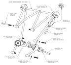
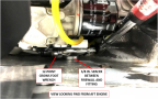
11. Loosely attach the engine at the aft two mounting points. (Figure 357) Install each bolt up from inside the fuselage with one washer under the head and with a self-locking nut with two washers under it. Do not tighten these fasteners yet.
12. Install the two forward engine mount bolts with one washer under each head. Do not tighten these fasteners yet.
Figure 357. Return Line Fitting and Firewall Clearance
13. Ensure that there is a clearance of approximately 3/8” between the firewall and engine oil return fitting using a 3/8” spacer. (Figure 358) If the clearance is less, lightly loosen the fitting and use a 7/8” 12-point crows foot wrench to torque the fitting. (Figure 359)
14. Remove the spacer.
Figure 358. Return Line Fitting and Firewall Clearance
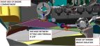
Figure 359. Engine Oil Return Line Fitting Torqueing Example
15. Torque the FWD and then AFT engine mount bolts to 330-350 in-lb.
16. Remove the engine hoist and 3/8” Anchor Shackle (x2).
17. Connect the engine harness to the ground studs on both sides of fuse box. Torque the M4 nuts to 8-11 in-lb.
18. Connect the three cannon plugs on top of fuse box.
19. Connect the regulator connectors, one on each side of fuse box.
20. Connect the fuel pump connectors in between the main bulkheads located near lower center of aft bulkhead.
21. Connect the HIC A and HIC B connectors near ECU.
22. Connect the three ECU connectors on ECU.
23. Install the aft bulkhead baggage panel.
24. Connect the grounding wire on the alternator. Torque fastener to 88 in-lb.
25. Apply INSULATING TAPE around the wiring at each firewall opening. This tape must lie between the wiring bundle and the firewall flange to seal and prevent chafing. Apply an outer wrap of insulting tape around the outside of the firewall flange and outside of inner tape wrap. Secure the outer tape with hose clamps until a compression seal is achieved.
26. Remove any plugs and connect the two coolant hoses from right and left side of radiator, and two coolant hoses at forward lower center of firewall bulkhead and install and tighten their band clamps.
27. Fill the cooling system with COOLANT per the latest Maintenance Manual: (Line Maintenance) For Rotax Engine Type 912 i Series
28. Connect the throttle cable to the engine throttle valve. Check and adjust throttle rigging. (Inspect
Throttle Control for Proper Travel and Security)
29. Remove any plugs and install oil feed hoses at thermostat. Torque B nuts to 150-250 in-lb.
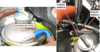
30. Remove plugs and install oil return hose at “IN” port of oil tank. (Figure 360) Torque B nut to 300-350 in-lb if using Method A or 290-330 in-lb if using Method B. (Figure 356)
CAUTION:
Ensure a back-up wrench is used on the oil tank fitting while torqueing. Damage to oil tank may occur if it’s not used.
Figure 360. Engine Oil Tank Return Hose Fitting Torqueing and 7/8” 12-Point Crows Foot Special Tool
31. Install the propeller, extension and fan as an assembly onto the engine propeller flange with the eight AN5C20A bolts and MS21043-5 nuts. Torque bolts in standard opposing sequence (1-4-2-5-3-6), first torqueing all bolts to 110 in-lb, then 170 in-lb and finally, 230 in-lb. Recheck torque of all bolts at 230 in-lb.
33. Purge the engine oil system per the latest Maintenance Manual: (Line Maintenance) For Rotax Engine Type 912 i Series.
34. Remove any protective covering from throttle valve and install the induction air duct and install and tighten its band clamps.
35. Remove any plugs and connect the -6 fuel supply and return lines at fuel rails. Torque fuel line B-nuts (4 locations) to 99-117 in-lb.
36. Connect the AAPTS sensor connector (near induction air filter).
37. Connect the signal and ground wires at started solenoid. Torque M6 nuts to 36 in-lb.
38. Install the exhaust system and exhaust shields. (Install Exhaust System (00001-00109)) (Install Exhaust System (00110+))
40. Connect all ground cabling to the aircraft’s battery ground terminal.
Verification Method
Complete the engine test run. (Engine
Test Run)
Parent topic