Remove Fuel Level Sensor
100190-00
Use the following task to remove the fuel level sensor.
Applicable Aircraft Serial Numbers
00021+
Type of Maintenance
Line
Level of Certification
LSA-RM
Task Specific Training Required
No
Special Tools Required
None
Parts Required
ICA011319 (PROBE, FUEL LEVEL SENSOR)
ICA012903 (GASKET, FUEL SENSOR)
ICA011512 (GASKET, ACCESS PLATE, FUEL TANK)
Aircraft System and Number
10—Instruments (and Avionics)
Safety Equipment
As Needed
Consumables
TT-I-735A or equivalent (ISOPROPYL ALCOHOL)
TY23MX (CABLE-TIE, NYLON 6-6, 18LB, TY-RAP)
TY24MX (CABLE-TIE, NYLON 6-6, 30LB, 5.50, TY-RAP)
LOCTITE 243 (THREADLOCKER, PRIMERLESS, OIL TOL, REMOVABLE MED STR, BLUE)
ICA012861 (SEALANT, GASKET, FUEL RESISTANT)
Task Instructions
3. Disconnect fuel level sensor connector from D9039P aircraft wire harness. Cut the zip ties securing the wire harness.
a. Loosen bolt on the Coarse Fuel Filter clamp.
b. Disconnect the Exterior Supply Line from the Supply Line Fitting on the Fuel Tank Access Plate.
c. Cap and plug open lines throughout.
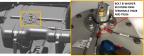
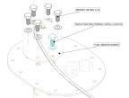
a. Use a 7/16 wrench to remove bolt, washer, and ring terminals T9028 and T9026 from the Fuel Level Sensor.
b. Disconnect the Fuel Level Sensor connector from D9039P on the Main Fuselage Wire Harness.
c. Remove three cable ties securing the Fuel Level Sensor harness and the T9028 ground wire to the Fuel Tank.
Figure 287. Coarse Fuel Filter Clamp and Exterior Supply Line
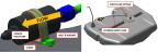
Figure 288. Coarse Fuel Filter Clamp and Exterior Supply Line
6. Remove the Fuel Level Sensor Assembly.
b. Slowly raise the Fuel Level Sensor assembly out of the Fuel Tank. Do not pull it out of the tank completely because interior tubing is still attached to it.
d. Completely remove the Fuel Level Sensor assembly out of the Fuel Tank.
Figure 289. Remove FUEL TANK ACCESS PLATE
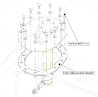
Figure 290. Fuel Level Sensor Assembly
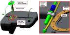
a. At the bottom of the Fuel Level Sensor, remove 2x Torx screws from the clamp bracket.
c. Remove the Fuel Level Sensor Probe and Fuel Tank Access Gasket from the Fuel Access Plate.
Figure 291. Clamp Bracket & Hardware
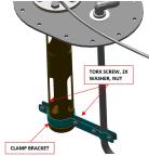
Figure 292. Fuel Level Sensor Probe Installation
Verification Method
Install new Fuel Level Sensor. (Install Fuel Level Sensor)
Parent topic